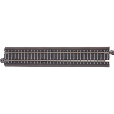
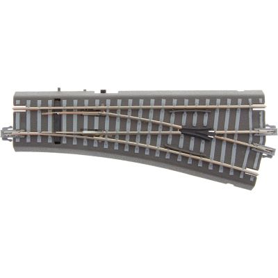
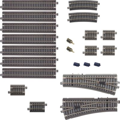
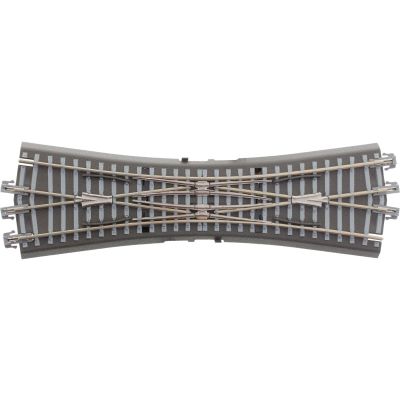
Grey Tillig Track with Roadbed
The grey version represents a lighter ballast bed. It is particularly suitable for main lines, modernised stations and clearly defined visible track formations.


The complete illustrated overview of Tillig TT track with roadbed: grey and brown straights, curves, compensation pieces, connection tracks, turnouts, crossings, uncoupling tracks, joiners, drives, multipacks and complete extension sets.
Range reviewed:
With Tillig TT roadbed track, the rail profile, sleepers and a moulded ballast body form one track element. The sections are connected using the UniJoiner system. This creates a stable connection suitable for both permanent model railway layouts and arrangements that are modified frequently.
The track system belongs to the TT nominal size at a scale of 1:120. The model track gauge is 12 millimetres. Many track sections are also used for H0m at a scale of 1:87, because H0m also runs on 12-millimetre track. TT represents standard gauge, while H0m represents metre-gauge prototypes. Vehicles, buildings, platforms and figures must therefore match the selected scale.
The integrated roadbed accelerates assembly on a table, layout board or display base. An additional cork underlay and complete ballasting are not required for the initial construction. On a permanently landscaped layout, the roadbed edges can nevertheless be blended into the scenery using fine ballast, soil, vegetation and platform edges.
Tillig supplies the basic geometry in grey and brown roadbed colours. The technical dimensions and connection elements are coordinated. Both colours can therefore be combined within one track plan. For a consistent appearance, however, one colour is generally preferable within each visible route section.
The grey version represents a lighter ballast bed. It is particularly suitable for main lines, modernised stations and clearly defined visible track formations.
The brown roadbed has a more earthy appearance and is especially suitable for branch lines, older stations, industrial connections and tracks that are more strongly integrated into the surrounding landscape.
The basic geometry consists of several straight lengths and curved sections with angles of 30 or 15 degrees. Twelve 30-degree curves or 24 15-degree curves form a complete circle. The minimum radius stated by the vehicle manufacturer should also be considered in every track plan.
| Track Designation | Length or Radius | Angle | Track Sections per Circle | Typical Application |
|---|---|---|---|---|
| BG1 | 166 mm | Straight | – | Long straights and the basic geometry grid |
| BG2 | 83 mm | Straight | – | Half a BG1 length and track compensation |
| BG3 | 43 mm | Straight | – | Turnout formations and short corrections |
| BG4 | 41.5 mm | Straight | – | One quarter of the basic length |
| BG5 | 36.5 mm | Straight | – | Compensation beyond turnout branches |
| BR11 | Radius 310 mm | 30° | 12 sections | Compact inner track circle |
| BR12 | Radius 310 mm | 15° | 24 sections | Partial curve and geometric compensation |
| BR21 | Radius 353 mm | 30° | 12 sections | Outer parallel circle |
| BR22 | Radius 353 mm | 15° | 24 sections | Turnout connection and partial curve |
| BR31 | Radius 396 mm | 30° | 12 sections | Generous outer curve |
| BR32 | Radius 396 mm | 15° | 24 sections | Large partial curve and turnout geometry |
In TT, a model track gauge of 12 millimetres represents a standard-gauge railway. Vehicles and accessories are selected at a scale of 1:120.
H0m also uses a 12-millimetre track gauge but represents metre-gauge prototypes at the larger H0 scale.
A transition to model track without roadbed can be created for freely designed routes. Suitable joiners and accurate height compensation are required.
Every item receives its own product card containing the catalogue number, description, roadbed colour, permanently assigned product image and direct link. The search accepts entries such as “83701”, “BR31”, “brown”, “turnout”, “connection track” or “station”.
Track with roadbed combines quick assembly with clearly defined geometry. It is suitable for beginners, changing arrangements and permanent layouts where a preformed track body is preferred.
The stable connection and roadbed body protect the sleepers and rail profiles. The track plan can be altered easily and expanded in stages.
The track can be fixed to a layout board and ballasted along the sides. Scenery and platforms are adapted to the height of the moulded roadbed.
The 12-millimetre track gauge also suits H0m. Buildings, vehicles, platforms and figures must then correspond to 1:87 scale.
Compare the planned radii with the specifications for your longest locomotives and vehicles.
Define the radius and colour before adding the station, parallel circle and storage tracks.
Positions for turnout drives, power feeds and isolated sections should be defined at an early stage.
Test every route using different vehicles before fixing the track permanently.
The track can be used for analogue and digital operation. When a connection track contains an interference-suppression capacitor, follow the instructions for the digital command station being used. Power can alternatively be supplied through rail joiners with a connection element.
These answers help with roadbed colour, track gauge, radii, digital operation, turnout control, transitions and selecting a suitable extension set.
The rails, sleepers and moulded ballast body form one track element. A separate roadbed is therefore not required for the initial assembly.
The geometry is identical. Grey resembles lighter ballast, while brown has a more aged or earthy appearance. Both colours can be connected technically.
Yes. The rails can be used with analogue or digital control. When connection tracks contain an interference-suppression capacitor, follow the instructions for the relevant digital command station.
TT and H0m both use a 12-millimetre model track gauge. H0m, however, represents metre gauge at 1:87 scale, while TT represents standard gauge at 1:120 scale.
The important circle radii are 310, 353 and 396 millimetres. Curves with angles of 30 and 15 degrees and suitable transition and compensation pieces are available.
A complete circle consists of twelve 30-degree curves or 24 15-degree curves. For an oval, equally long straight sections are added between the semicircles.
The roadbed body is designed for the system-specific drives. Electric drive 83960 is used for standard turnouts; double-slip turnouts without a drive can be equipped with 08335.
Yes. Suitable rail joiners and height compensation beneath the track without roadbed are required. The transition should be straight and free from tension.
The roadbed system uses fixed track elements. For completely free radii, a transition can be made to Tillig TT model track using flexible track.
Extension set 01833 adds station tracks and turnouts to a basic circle. Larger combined sets also connect the oval with a parallel circle or shunting area.
Both sets develop a parallel circle in stages. Part 1 creates the first parallel route, while Part 2 completes the further expansion.
Yes. The transitions between the roadbed and surrounding scenery can be adapted using fine ballast. Adhesive must not enter joiners, point blades or moving drive components.
Further guidance about gauges, layout planning, digital operation, landscaping, maintenance and rolling-stock selection is available on the central guide page.