Modellbahn Keks
Welcome!
Our cookies offer you a fast, relaxed and full-featured shopping experience. Some are necessary to operate the website and its functions. Others help us to improve our services. If you agree to this, simply consent to the use of cookies for preferences, statistics and marketing by clicking on "OK". Alternatively, you can deactivate individual cookies under "Customise cookies" or all cookies, except those required for the function of our website, under "Reject all".
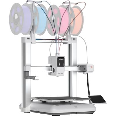
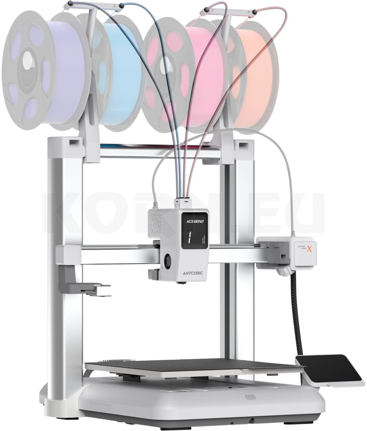
Anycubic Kobra X FDM 3D Printer for custom-designed model parts
Model making in 1:87 scale

3D Printing for H0 – Projects, Settings and Limitations

FDM often works well for buildings, walls and larger accessories. Resin offers advantages for detailed figures, delicate fittings and small surface features. The key is to design parts for printing, choose suitable settings and test before producing a batch.

From project to process

Which H0 projects are good for beginners?

3D printing for H0: projects and settings go hand in hand. Start with a manageable part that has only a few critical features. A tool shed or loading ramp is more forgiving than a locomotive lamp with thin brackets. The selection below helps you assess the effort and level of detail involved.

Six typical applications on an H0 layout
Project Suggested approach What to check
Platform shelters and building walls FDM for broad surfaces; separate windows if needed Separate walls and roof, provide gluing edges and protect visible surfaces.
Tunnel portal and retaining wall FDM for larger structures Check mortar joints in the slicer; allow sufficient clearance on curved track.
Benches, crates and platform signs FDM for robust shapes, resin for small details Strengthen legs; apply lettering separately if needed.
Vents, lamps and vehicle fittings Resin for fine surface detail Test mounting pins and holes; use an alternative construction for fragile brackets.
Standing and seated figures Resin where high detail is required Check hands, feet and supports; plan for painting.
Drilling templates and assembly jigs FDM, with material chosen for the loads involved Check fit, abrasion and load direction; consider areas subject to wear.

A single project can combine several techniques: printed walls, clear glazing film, wire railings and ready-made figures work well together. This puts detail where it is visible without making every part unnecessarily complicated to print.

Transfer dimensions correctly

What does 1:87 mean when designing?

For H0, divide a full-size dimension by 87. One metre becomes approximately 11.49 millimetres on the model. A person 1.80 metres tall becomes about 20.69 millimetres high. First convert all starting dimensions to the same unit. When importing an STL file, check the actual external dimensions in the slicer.

To enlarge a 1:160 file to H0, use 160 ÷ 87 × 100 = approximately 183.91 per cent. From 1:120 to H0, use about 137.93 per cent. Reduce a 1:76 model to approximately 87.36 per cent. Afterwards, check wall thicknesses, fits and the smallest details again.

The calculation alone does not determine printability. A railing tube with a full-size diameter of 30 millimetres would be only about 0.34 millimetres in H0. Such parts may fail to print, break during support removal or become damaged later when handled.

Start with a controlled approach

Choose nozzles, layer heights and wall thicknesses

These ranges are our suggested starting points for your own test pieces, not validated profiles for every machine. Begin with the manufacturer's profile for your printer, the nozzle actually fitted and the specific material. Our wall thicknesses are design suggestions for small model parts, not guaranteed technical minimums.

Starting ranges for different levels of detail
Application Nozzle and layer height Suggested design wall thickness
FDM buildings and walls 0.4 mm nozzle; approximately 0.12–0.16 mm layer height Approximately 1.2–1.6 mm; reinforce large surfaces as well.
Small FDM accessories Approved 0.2 or 0.25 mm nozzle; approximately 0.08–0.12 mm Approximately 0.6–0.8 mm for small, protected walls; make freestanding parts stronger.
Resin accessories and figures No nozzle; start with a suitable 0.05 mm profile and compare 0.03 mm where useful Allow approximately 0.8–1.2 mm for small housings; assess thin limbs separately.
FDM assembly jigs 0.4 mm nozzle; approximately 0.20 mm where surface finish is less critical Design for the load; include extra perimeters and reinforcement.

A finer layer does not replace a finer outline

Layer height affects stepping in the Z direction. A smaller nozzle, by contrast, changes what is possible with narrow extrusion lines in the printing plane. Prusa gives an example extrusion width of 0.45 millimetres for a 0.4 mm nozzle. Several perimeters provide only an approximate wall thickness; the slicer and profile determine the actual toolpath.

Check every critical feature in the layer preview. If a window mullion disappears there, address it with suitable geometry or a different print profile. Reducing layer height alone will not solve it. Small nozzles need suitable profiles and filaments; particle-filled materials can be problematic.

Match temperature, speed and exposure

For FDM, use nozzle and bed temperatures from the appropriate material profile. For tiny parts, also check cooling and minimum layer time. A high advertised maximum speed says little about the quality of an H0 lamp. When testing, change only one relevant setting at a time wherever possible.

For resin, exposure time and motion settings depend on factors including the printer, resin, temperature and layer height. Do not copy exposure times from a different printer model. Start with the appropriate manufacturer's guidance, then calibrate. A finer layer requires another check; it guarantees neither clear holes nor walls free from distortion.

Choose material for the location and loads involved

PLA is a natural starting point for decorative building parts used indoors. Still, avoid prolonged heat exposure, such as directly beside hot components or behind windows in strong sunlight. A model may face different conditions in everyday use from those on the workbench.

PLA+ covers different formulations rather than a single standardised material property. Compare the specific manufacturer's data. PETG may be useful for brackets and assembly jigs under load; test its suitability for very fine details with your own sample. Changing material family does not replace a suitable design.

With resin, balance detail, stiffness and the toughness you need. A small relief and a frequently handled handrail have different requirements. Also check whether your printer can process the resin and what cleaning and post-curing it requires.

A larger 0.6 mm nozzle can speed up printing large, hidden FDM substructures, but is rarely the first choice for delicate H0 windows. Consider the main body and visible details separately. Save the appropriate profile and material name for recurring parts. This makes later reprints easier to compare, even if you have since tried another filament.

A clear worked example

A small shelter for an H0 platform

The following design example describes a possible workflow, not a documented print test. The plan is for an open shelter with three walls and a removable roof. The full-size starting dimensions are three metres wide, two metres deep and 2.40 metres high at the walls.

Prepare materials and tools

You need a suitable PLA filament, an FDM printer with an appropriate profile, CAD software, a slicer, callipers, a fine file, abrasives and an adhesive suitable for the materials. Add primer and paint after checking the fit. Glazing film or a separate bench can complete the shelter.

1

Define dimensions and separate parts

Rounded dimensions give a footprint of 34.5 × 23.0 millimetres and a wall height of 27.6 millimetres. Start with a wall thickness of 1.35 millimetres. Allow for material thickness at joints so the finished external dimensions are correct. Design the roof separately, for example 36.5 × 25.0 millimetres and 1.2 millimetres thick.

2

Print a wall section first

Test a corner with the intended joint and surface texture. For example, start with a 0.4 mm nozzle and a layer height of 0.16 millimetres. Check the perimeters in the slicer. A short test print shows whether the gluing edge, wall and desired details work together.

3

Check visible surfaces and fit

Print suitable flat walls with their backs on the bed. Check the surface appearance; the underside may take on the bed texture. Keep supports away from visible façades. Dry-fit the shelter first and check that it is square and the roof sits correctly.

For a plug-in joint

Compare test pieces with, for example, 0.15, 0.25 and 0.35 millimetres of clearance per side. These values are only a test series. Material, orientation and calibration determine the right fit.

Allow for paint thickness

Check the chosen joint again with your primer and paint applied. Keep gluing surfaces clear wherever possible and avoid thick paint layers on fine details.

4

Assemble and check on the layout

Deburr the parts, glue the walls square and fit the roof. Place the shelter beside the track before fixing it permanently. Check that your longest and widest vehicles can pass. For advice on the surrounding scene, see the guide to planning and designing platforms.

Add windows, downpipes or signs only once the main structure works. For mixed construction methods, find ideas in the guide to scratch-building buildings and suitable building accessories. Record the file version, material and profile so you can reproduce parts for later additions.

A practical approach to detail

The limitations of H0 printing

Figures and vehicle details need a margin of strength

A freestanding handle has to withstand more than a relief on a solid wall. Deliberately reinforce vulnerable transitions or use wire and etched parts. A suitable, tougher resin formulation may help; the word resin alone does not indicate a particular resistance to breakage. Material data and geometry must work together.

Manufacturers' stated minimum feature sizes apply to specific printers, resins and test conditions. They are not a universal guarantee for any H0 model. Screen resolution, pixel size, exposure and supports work together. Pay particular attention to unsupported areas beneath arms, buffers and roof overhangs.

Large surfaces, cavities and supports

Broad resin surfaces can warp during printing or post-curing. Choose orientation and supports according to the geometry; a single standard angle will not solve every problem. Avoid sealed cavities containing trapped resin. Hollow models need suitable openings and a cleaning and post-curing process that can be completed throughout the model.

For FDM, sensible part division and strong gluing edges help. Thin panels may consist entirely of top and bottom layers, so increasing infill does little. Reinforcing ribs and suitable perimeters can be more effective than simply adding more infill.

Running trains requires more than attractive surfaces

For platform edges, bridges and tunnel portals, vehicle clearance matters. Use the MOROP NEM 102 and 103 standards; NEM 104 is relevant for narrow gauge. Curves create additional sideways overhang. Check your actual track geometry, vehicles and overhead wires where applicable before final installation.

Coupling pockets, bearing seats and gears are demanding functional parts. Dimensional accuracy, wear, friction and sustained loads all matter. Start vehicle conversions with decorative parts and use suitable, proven components for critical functions.

Post-processing is part of the project

For resin, follow the manufacturer's instructions and safety data sheet, including suitable gloves, eye protection and ventilation. Wash, dry and post-cure according to the material instructions. Even water-washable resin does not make contaminated wash water suitable for the drain. Collect residues and dispose of them in accordance with local requirements.

Narrow down common print faults systematically

  • Missing details: first check the file and scaling, then the slicer preview. Only then change the nozzle, line width or exposure.
  • Window openings are too tight: measure the external dimension and opening separately. Check FDM first-layer spread or resin exposure; do not immediately scale up the entire building.
  • Long walls are warped: investigate bed contact, material profile, orientation and supports. For resin, also consider cleaning and post-curing.
  • Railings break: look at the stressed area and support contact points. Strengthen transitions or switch to wire before printing a whole batch unchanged.

Also assess test pieces from their eventual viewing distance. A macro photograph reveals layers that may barely be noticeable on the layout. What matters is convincing proportions, clean edges and parts that can be assembled reliably.

Explore the manufacturers' ranges

Compare printers, materials and accessories within each system.

Equipment for your H0 projects

Find printers, filaments and resins

Search by product, material, colour or item number. Combine process, category and manufacturer filters. The list loads current products from the linked categories. Check printer compatibility and material properties on the product page.

The product list is being prepared. You can open the categories directly.

View all 3D tools

Frequently asked questions about printing in 1:87

Is a 0.4 mm nozzle sufficient for H0?

Yes, for many buildings, walls, plinths and robust accessories. Very thin struts and tiny outlines may require a smaller approved nozzle, a revised design or resin. Decide using a representative test part.

Are 0.03 mm layers always better for resin?

No. Finer layering can improve sloping surfaces but increases the number of layers. Exposure and geometry remain crucial. Compare 0.05 and 0.03 millimetres on the same model using suitable profiles.

Can I print H0 figures with FDM?

Simple or deliberately stylised figures are possible. However, at a body height of around two centimetres, fine facial features, fingers and freestanding arms become challenging. Resin is often more suitable for such details.

Is a file labelled “HO” automatically suitable?

HO is commonly used for H0. Still check the stated scale, external dimensions and wall thicknesses suitable for printing. A filename alone confirms neither fit nor printability.

Can I use the same file for H0m and H0e?

Often yes for scale buildings or figures, because both use 1:87. Track-related parts, vehicles and clearances must match the particular gauge and prototype.

Does every model have to be entirely printed?

No. Printed parts can be combined with sheet materials, glazing film, wire and ready-made accessories. Especially for fragile details, mixed construction can make assembly and later handling easier.

Technical background: MOROP standards (German), Prusa on designing for 3D printing, Prusa on nozzle diameters, Anycubic on resin parameters and Formlabs on printer-specific design limits. Further reading: Resin print orientation and Liqcreate on water-washable resins. The project dimensions and starting ranges are our own planning examples.

From your first part to your own H0 scene

Find more fundamentals in the 3D printing knowledge hub. Combine suitable printing technology with careful model making.

Explore the model railway guide