Flexible Track for Natural Routes
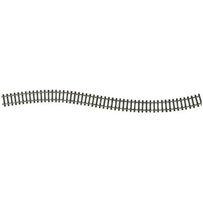
Long flexible track permits free radii, transition curves and flowing routes without being restricted to a fixed geometric grid.


The illustrated product overview of Fleischmann N track without integrated roadbed: flexible track, straights, short compensation sections, fixed radii, connection and functional track, manual turnouts, electric turnouts, curved turnouts and crossings.
Range reviewed:
Fleischmann N track without roadbed has no permanently moulded ballast body. The rails and sleepers are laid on a prepared track base. The height, colour, width and weathering of the finished track bed can therefore be designed individually.
The track system belongs to N gauge at a scale of 1:160. The model track gauge is 9 millimetres. It is intended for the standard two-rail direct-current system and can be used as the track foundation for analogue or digitally operated layouts.
Flexible track measuring 730 millimetres permits flowing routes and transition curves. Prefabricated straight track and fixed radii provide precisely repeatable geometry in stations, hidden yards and parallel routes.
Short compensation sections close remaining gaps. The system is supplemented by a rerailer track, connection track, uncoupling track, sleeper-end pieces, manual turnouts, electric turnouts, curved turnouts and an electric crossing turnout.
The system is particularly suitable for permanent layouts, modules, sections, stations and individually landscaped routes. Complete train operation should be tested thoroughly before the track is fixed permanently and ballasted.
Long flexible track permits free radii, transition curves and flowing routes without being restricted to a fixed geometric grid.
Defined lengths, angles and radii simplify parallel circles, station tracks, turnout formations and concealed storage areas.
The substructure, sound insulation, ballast colour, trackside paths and embankments can be designed to match the prototype being represented.
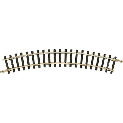
The fixed curved products range from compact radius R1 to generous radius R7. The technically possible radius should always be compared with the required minimum radius of the locomotives and coaches being operated.
| Geometry | Radius | Angle | Products | Typical Application |
|---|---|---|---|---|
| R1 | 194.6 mm | 30°, 24° and 6° | 22221, 22231, 22232 | Compact layouts and connections to 24-degree turnouts |
| R2 | 228.2 mm | 30°, 24° and 6° | 22222, 22233, 22234 | Second compact parallel circle and compensation curves |
| R3 | 261.8 mm | 30° | 22223 | Medium circle and visible branch line |
| R3a | 295.4 mm | 30° and 15° | 22224, 22235 | Larger parallel circle and fine angle compensation |
| R4 | 329 mm | 15° | 22225 | Visible routes and longer vehicles |
| R5 | 362.6 mm | 15° | 22226 | Radius matching the 15-degree turnout geometry |
| R6 | 480 mm | 15° | 22227 | Generous visible main lines |
| R7 | 765 mm | 12° | 22228 | Very large compensation and reverse curves |
| Flexible Track | Individual | Freely planned | 22200, 22201 | Transition curves and freely flowing routes |
Small radii save space but are not suitable for every vehicle. Long passenger coaches, express locomotives and multiple units benefit from larger curves.
For connection track 22220, observe the relevant product instructions and the installed suppression component, particularly when using a digital power supply.
A level, torsion-resistant track base remains necessary. Sound insulation, track fixing, functional testing and ballasting can then follow.
Every product receives its own card with a catalogue number, precise description, permanently assigned main image and direct product link. Search terms can include “22200”, “flexible track”, “R3a”, “uncoupling track”, “left-hand turnout” or “22275”.
The advantages of the track system are most apparent when radii, flexible track, turnouts, power feeds and the future scenery are planned together.
Short straights, compensation sections, 24- and 15-degree turnouts, curved turnouts and the crossing turnout permit different station approaches.
Flexible track and larger radii create flowing routes. The individually constructed ballast bed also defines the character of the line.
Invisible areas must also remain operationally reliable, adequately supplied with power and accessible for maintenance work.
Check the minimum radius of the longest locomotives, coaches and multiple units. Visible routes benefit from larger radii.
The track base, insulation and centreline must be level and accurately prepared. Track must not be laid under tension.
Power feeds, isolation points, uncoupling track and turnout drives should be defined before permanent fixing.
Test every route with different vehicles. The track should be detailed permanently only after reliable operation has been confirmed.
Flexible track should be cut cleanly and fixed without tension. Adhesive and ballast must be used particularly sparingly around point blades, frogs, operating mechanisms and electric drives.
The following answers provide guidance about track gauge, radii, flexible track, connection products, compensation track, turnouts and individual ballasting.
The rails and sleepers have no integrated ballast body. The track is laid on a prepared base and then fixed and ballasted individually.
The model track gauge is 9 millimetres. N gauge uses a scale of 1:160.
The track can be used on a digitally operated two-rail layout. For connection track 22220, the instructions and installed suppression component must be considered.
The overview ranges from R1 at 194.6 millimetres to R7 at 765 millimetres. R2, R3, R3a, R4, R5 and R6 are positioned between them.
Twelve curved sections with an angle of 30 degrees form a complete circle. Twenty-four sections are required for 15-degree curves.
Both track products are 730 millimetres long. Product 22200 is flexible track, while product 22201 is a rigid flexible-track section.
Products 22205, 22206 and 22207 close small differences in length in stations, parallel routes and turnout connections.
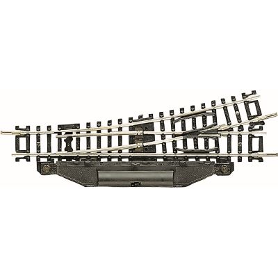
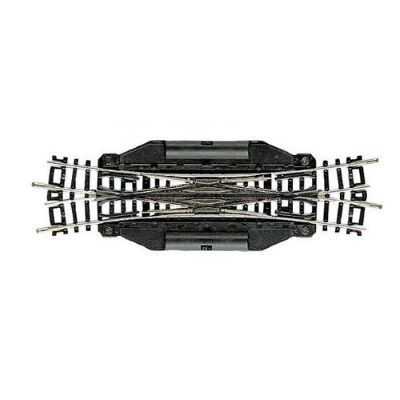
The overview includes short 24-degree turnouts, longer 15-degree turnouts, R1/R2 curved turnouts and an electric crossing turnout.
The left- and right-hand turnouts have a diverging angle of 15 degrees and a diverging radius of 362.6 millimetres.
Curved turnouts 22273 and 22275 divide a curved route between the compact R1 and R2 radius ranges.
The rerailer track makes it easier to place vehicles correctly on both rail profiles.
The track should be ballasted only after every connection, turnout, power feed and route has been tested reliably with different vehicles.
Plan radii, turnouts, power feeds, train lengths and maintenance access together before fixing and ballasting the track permanently.