Basic Roadbed-Track Set
TT Track Oval
Compact basic formation for test running, initial operation or later expansion.
View track oval
This overview brings together 32 Tillig TT track sets: five preconfigured complete roadbed-track sets, four systematic extension sets and 23 model-track packages for specific layout plans. It also explains how straights, radii, flexible track, turnouts, crossings and electrical isolation points work together.
TT gauge uses a scale of 1:120 and a model track gauge of 12 millimetres. Its space requirements lie between H0 and N: trains already appear substantial and detailed, while stations, double-track routes and longer running distances fit more easily onto a typical home layout than they would at larger scales.
A track set combines compatible pieces for a specific purpose. This may be a simple oval, a station extension, a second circuit, a shunting area or the complete track package for a developed layout plan. Straights, curves, turnouts and compensation pieces therefore do not have to be collected individually from a long parts list.
Tillig primarily distinguishes between fine-looking Model Track without moulded roadbed and Roadbed Track with an integrated ballast base. Both use a track gauge of 12 millimetres but differ in installation height, connectors, geometry and scenic treatment. A new layout should therefore begin with a clear choice of system.
The 23 layout packages named after locations contain coordinated track for a specific plan. The five complete roadbed-track sets, by contrast, create clearly defined basic track formations. Four additional Tillig sets expand an existing roadbed-track layout specifically with a station, parallel circuit or marshalling yard.
Important: A track-plan set is primarily a package containing the required track components. Vehicles, buildings, scenery, control equipment and other accessories are included only when the relevant product page expressly lists them as part of the set. Dimensions and track lengths follow the set illustrations.
The choice depends less on analogue or digital operation than on the method of construction, desired appearance and later expansion. Track from both systems can be used for either operating method; the power supply, wiring and controller determine how trains are run.
| Feature | TT Model Track | TT Roadbed Track |
|---|---|---|
| Construction | Fine sleeper base without a moulded ballast body | Track and shaped roadbed form a stable system unit |
| Typical Use | Permanently installed layouts with individually applied ballast | Quick assembly, starter layouts, test tracks and gradual expansion |
| Scenic Treatment | Free choice of base, ballast colour and surrounding scenery | Complete track appearance immediately; the sides can still be detailed |
| Geometry | Straights, numerous radii, flexible track, turnouts, crossings and double slips | Connectable BG and BR geometry with straight and curved turnouts |
| Set Selection | 23 complete track packages organised by layout plan | Five complete sets and four coordinated extensions |
| Particular Strength | Prototypical track appearance and flexible alignment | Straightforward planning and quick, tidy assembly |
Their common track gauge does not provide a direct plug-in transition. Roadbed height, connectors and geometry must be compensated at a planned transition point. Reliable operation requires a clearly defined system change with suitable height adjustment, accurately aligned rail profiles and test running before the track is fixed permanently.
These five packages range from a compact oval to a layout with two circuits, a station and a shunting area. The stated base dimensions make comparison with a table, layout board or available room easier.
Compact basic formation for test running, initial operation or later expansion.
View track oval
A parallel station track is added to the oval for train crossings and overtaking movements.
View station set
An additional route section increases the running distance and operating possibilities.
View Parallel Circuit 1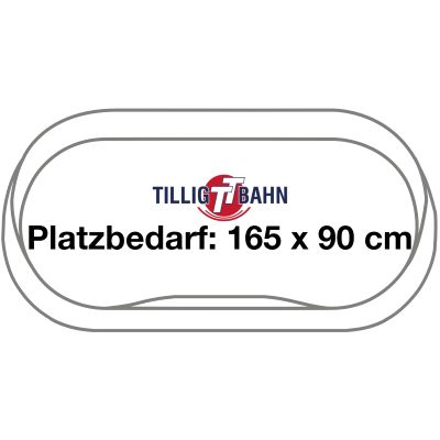
Two closed routes and the station area permit varied simultaneous train operation.
View two-circuit set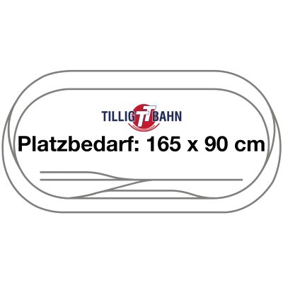
The most extensive basic roadbed-track formation combines continuous running, a station and storage sidings.
View complete setCatalogue numbers 01833 to 01836 each solve a specific task. They can add a passing track, parallel route or several storage sidings to an existing basic layout without requiring every compensation piece to be determined individually.
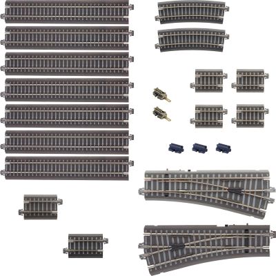
Two 15-degree turnouts, straights, curves and connectors for power feeds and electrical isolation.
View set 01833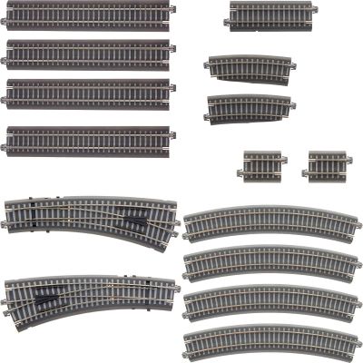
Curved turnouts, matching curves and straight sections begin the second running route.
View set 01834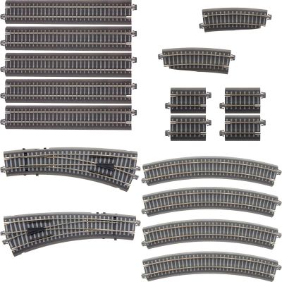
Two curved turnouts and coordinated curves and straights complete the extension.
View set 01835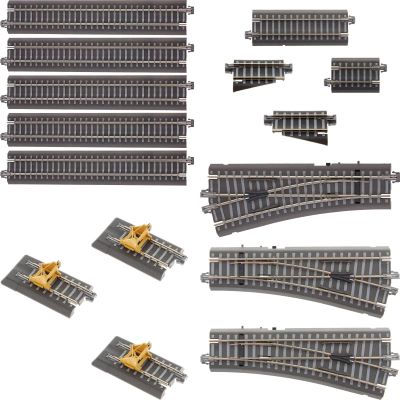
Three turnouts, several straight tracks and three buffer stops form a group of storage sidings.
View set 01836The place names identify different track-plan concepts. In addition to the maximum layout width and depth, track length provides a useful indication of complexity. A shorter plan may deliberately focus on straightforward branch-line operation, while longer track routes normally include more station tracks, concealed sections or storage facilities.
Suitable for small layout rooms, first permanent TT layouts and clearly defined projects.
Larger stations, longer running distances and the first complex turnout formations within a home-friendly area.
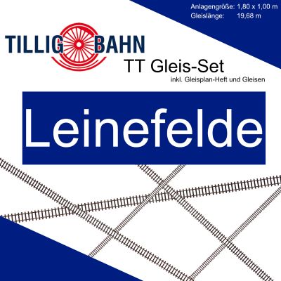
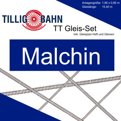
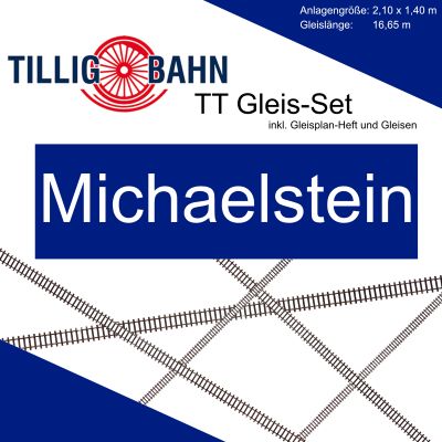
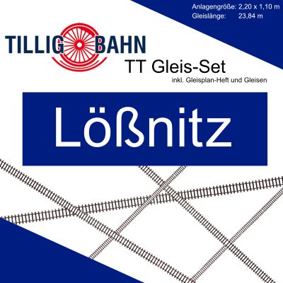
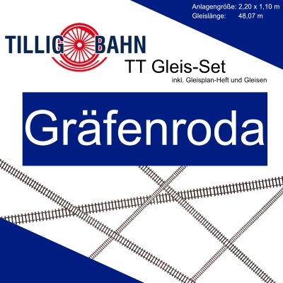
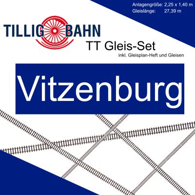
Suitable for long routes, extensive stations, hidden sections and varied model railway operation.
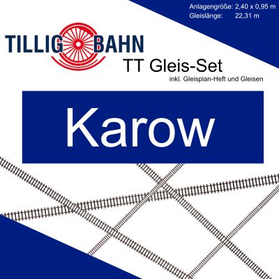
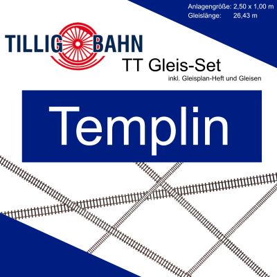
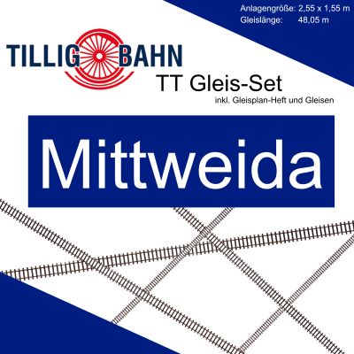
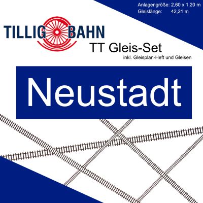
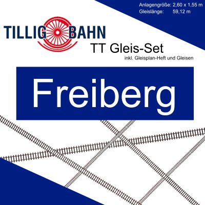
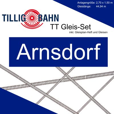
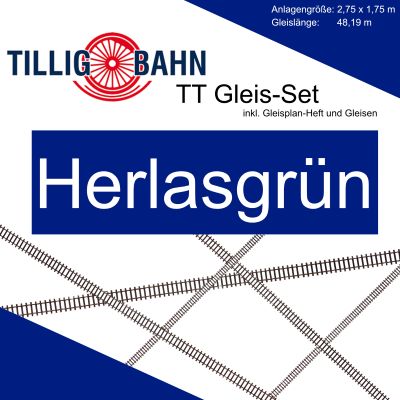

Track length alone does not determine the required area. Levels, gradients, concealed routes and the arrangement of curves can produce substantially different quantities of track on two layouts of a similar overall size.
Product designations follow systematic geometry. Understanding the basic types makes parts lists easier to read, permits existing plans to be modified and helps when adding suitable track , turnouts or track accessories .
In the Model Track system, G1 is 166 mm long, G2 is 83 mm, G3 is 43 mm, G4 is 41.5 mm, G5 is 36.5 mm and G6 is 21.5 mm. The short sections close gaps beside turnouts or return parallel tracks to the system geometry.
R11 and R12 use a radius of 310 mm, R21, R22 and R24 use 353 mm, and R31 and R32 use 396 mm. The second digit identifies different curve angles. Larger radii produce a smoother appearance; the permitted minimum radius must also be checked for the relevant vehicle.
Flexible track can be used for broad curves, gentle transitions and individual lengths. It is cut to size and aligned carefully. In visible areas it avoids unnecessary rail joints and supports a flowing route through the scenery.
Standard turnouts in the EW1, EW2 and EW3 families connect the main route and branch. Curved turnouts place both routes within a curve and therefore save length. Reliable operation requires the switch blades, frog, drive and electrical supply to be planned together.
A crossing allows two tracks to intersect at the same level. A double slip combines a crossing with turnout functions in one component. It saves space but requires especially accurate installation, correctly working drives and reliable frog polarisation.
Rail joiners align the profiles and carry current. Joiners with connection tabs simplify power feeds, while insulated joiners separate electrical sections. On larger layouts, additional sensibly distributed feeds should supply power rather than relying solely on mechanical rail connections.
Corresponding roadbed-track straights are designated BG and curves BR. The moulded roadbed also determines the installation height. With Model Track, the base and ballast are selected separately. Suitable materials are available under track bedding .
A suitable set is not determined solely by its external dimensions. Accessibility, vehicle length, usable station length, gradients and electrical divisions determine whether the track plan can later be operated reliably and conveniently.
Allow space around the layout for operation, maintenance, wiring and removable access sections.
Choose Roadbed Track for quick system-based construction or Model Track for a layout with individually applied ballast.
Use the longest planned vehicle and its specified minimum radius as the determining standard.
Station, storage and hidden-yard tracks must accommodate the intended train lengths.
Plan power feeds, isolation points, occupancy detection and any reversing loops before constructing the scenery.
Lay the track loosely, test every type of vehicle and only then secure it permanently.
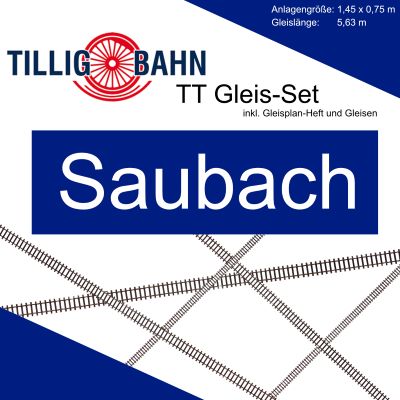
The track oval, Altenhof or Saubach provide straightforward starting points.
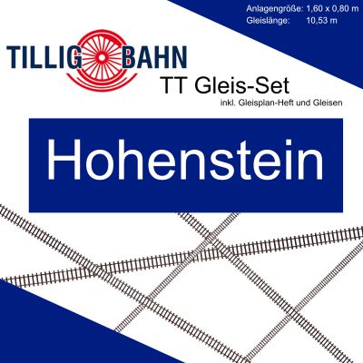
The station set, Hohenstein or Leinefelde combine continuous running with train crossings.
Parallel Circuits 1+2 provide two closed routes within a clearly defined area.
Freiberg, Großheringen and Großkorbetha offer extensive track for larger projects.
Further planning support is available in the guides Plan a Model Railway , Track Planning and the Model Railway Calculator .
The same model track gauge can represent different prototype gauges at different scales. Track should therefore not be selected solely by the distance between the rails. Scale, sleeper pattern, vehicle width, loading gauge and turnout geometry must also be suitable.
| Model Size | Scale | Model Track Gauge | Relationship to These Sets |
|---|---|---|---|
| TT | 1:120 | 12 mm | The 32 listed sets are intended for standard-gauge TT models. |
| TTe | 1:120 | 6.5 mm | Narrow gauge at TT scale; not interchangeable with standard-gauge TT track. |
| H0m | 1:87 | 12 mm | The same track gauge but a different scale and appearance. |
| H0e | 1:87 | 9 mm | A separate H0 narrow-gauge system using its own track. |
| H0 | 1:87 | 16.5 mm | Tillig ELITE and Standard are separate H0 track systems. |
H0m vehicles also use a model track gauge of 12 millimetres, but a TT track plan is not automatically suitable for H0m because of the larger H0 scale. Compare vehicle dimensions, track spacing, radii and structures. Further information is available in the gauge comparison , the H0m guide and the H0e guide .
These answers cover space requirements, system selection, power supplies and later expansion.
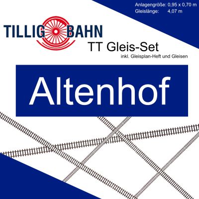
According to the set illustration, the roadbed-track oval requires approximately 70 × 85 cm. Among the complete Model Track layouts, Altenhof is the most compact listed plan at 0.95 × 0.70 m.
Model Track is supplied without moulded roadbed and can be supported and ballasted individually. Roadbed Track already has a shaped ballast base and is particularly suitable for quick and stable system-based construction.
Yes. The track is not limited to one control method. When converting to digital operation, however, the command station, vehicles, decoders, wiring and any existing analogue isolation circuits must suit the new operating concept.
Additional power feeds are sensible on extensive layouts. They reduce voltage losses across long routes and numerous rail joints. Their number and position depend on track length, electrical sections, turnouts and occupancy detection.
Not necessarily. The specification for the individual vehicle remains decisive. Long passenger coaches, steam locomotives and highly detailed models frequently benefit from larger radii.
G identifies straight track, R identifies curved track with a defined radius and angle, EW identifies a standard turnout and DKW identifies a double-slip turnout. The following digits distinguish length, radius, angle or design.
A transition must be planned deliberately. The systems differ in roadbed height and connection method. The rail heads must align precisely, the profiles must be joined securely and the height difference must be supported firmly.
Both use a model track gauge of 12 millimetres. H0m is nevertheless built at a scale of 1:87 and represents metre gauge. Sleeper pattern, loading gauge, radii and layout dimensions must therefore be checked separately.
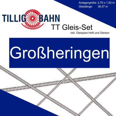
Großheringen is designed for an area of 2.70 × 1.50 m and, according to the set illustration, contains 38.37 m of track. The plan combines a station, several turnout connections, storage facilities, flexible track and a turntable area.
With Roadbed Track, Tillig 01836 adds three turnouts, several storage sidings and three buffer stops. Among the larger Model Track plans, Großheringen, Freiberg and Großkorbetha provide extensive track formations.

In addition to the track sets, explore individual straights, curves, turnouts, rail joiners and other accessories for the targeted expansion of your TT layout.