




Contact Shape
Six Openings Next to Each Other
The vehicle socket consists of a straight row containing six small contacts.

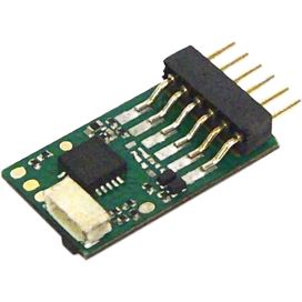
The compact NEM 651 interface connects the track, motor and front and rear lighting through six contacts. It is used particularly in N, TT, H0e and small H0 vehicles. This guide explains the pin assignment, installation rules and suitable decoders.
NEM 651 describes a standardised electrical connection between the vehicle circuit board and digital decoder. The vehicle side has a socket with six contacts arranged in one row. The decoder is connected directly or through a short wired connector.
The six contacts carry both motor connections, both track connections and the front and rear lighting. Unlike NEM 652, the basic interface does not have a dedicated common positive connection for the lighting or an unused standard contact for auxiliary functions.
The interface does not determine the digital format. An NEM 651 decoder may support DCC only, DCC and Motorola, Selectrix or several protocols. Sound decoders are also available with a six-pin connection.
The installation dimensions, connector orientation, motor current and protocol remain decisive. With direct versions in particular, check whether the decoder circuit board can extend straight, sideways or above the socket.
The vehicle socket consists of a straight row containing six small contacts.
A small blanking plug is often fitted to the socket at the factory to enable analogue operation.
An arrow, dot, number or circuit-board marking often identifies the installation direction.
Straight direct decoders require free space in line with the row of pins.
Angled pins are useful when there is insufficient space in the longitudinal direction.
A wired connector allows installation in a free location but requires additional room for the cable.
NEM 651 does not have a dedicated contact for a common positive return. The lighting return is therefore provided through the vehicle circuit board and a suitable circuit. Lighting return connections must not be connected directly to a rail without checking the circuit.
Additional function outputs may be available on the decoder but, with a six-pin direct version, they are normally connected through separate solder pads or wires.
| Contact | Function | Wire Colour | Connection | Check |
|---|---|---|---|---|
| 1 | Motor Connection 1 | Orange | Decoder to motor | Often identifies the installation direction |
| 2 | Motor Connection 2 | Grey | Decoder to motor | Motor must not be connected directly to the track |
| 3 | Right-Hand Track Pickup | Red | Right rail | Supplies the decoder with the track signal |
| 4 | Left-Hand Track Pickup / GND | Black | Left rail | Not a common positive connection |
| 5 | Front Lighting | White | Front driving light | Can be switched according to direction |
| 6 | Rear Lighting | Yellow | Rear driving light | Can be switched according to direction |
The six pins are mounted directly on the decoder circuit board. This version requires free space in line with the socket and does not require additional wiring.
Flat, elongated installation spaces in N and TT.
The row of pins is angled relative to the decoder circuit board. This allows the decoder to lie above or beside the vehicle circuit board.
Short locomotive bodies with little longitudinal space.
The connector is linked to the decoder using wires or a ribbon cable. The module can be secured in a free location.
Offset installation spaces and irregularly shaped bodies.
A function decoder switches lighting and special functions but does not have a regulated motor output stage.
Control cars and illuminated vehicles.
The six-pin connector carries the basic functions. The loudspeaker and additional outputs are connected separately.
N, TT and compact H0 sound conversions.
Additional function outputs, SUSI or energy storage may be accessible through small solder pads.
Experienced modellers with fine soldering equipment.
| Interface | Contacts | Typical Gauges | Strength | Limitation |
|---|---|---|---|---|
| NEM 651 | 6 | N, TT, H0e, H0m and small H0 | Very compact and simple | No common positive contact |
| NEM 652 | 8 | Mainly H0 | Common positive connection provided | Larger connector |
| Next18 | 18 | N, TT and small H0 | More outputs in a compact design | Not compatible with NEM 651 |
| PluX12 | 12 | TT and H0 | More auxiliary functions | Different pin arrangement |
| PluX16 | 16 | TT and H0 | Suitable for lighting and sound | Requires more installation space |
NEM 651 is widely used in N but is rare in Z. Very small decoder dimensions are essential.
Height and clearance from the flywheel or body.
The six-pin interface is frequently found in these gauges. Straight, angled and wired versions are all relevant.
The position of the socket and direction of the decoder board.
NEM 651 is used in small, older or narrow H0 vehicles. NEM 652, PluX and 21MTC are more common.
The motor current may be higher than with typical N decoders.
A six-pin socket is rare. Even when the connector fits mechanically, the motor may require more current than a micro decoder can provide.
Measure continuous and starting current under load.
NEM 651 is not normally intended for large-scale railways. High-capacity decoders with wires, terminals or PluG are more suitable.
Multiple motors, smoke units and powerful lighting.
The gauge provides only an indication. The socket actually fitted, installation height and motor output are decisive.
Open the locomotive, photograph and measure it, and compare the instructions.
The motor, current pickup and lighting must operate correctly.
Release screws, clips and wires according to the instructions.
Photograph the socket, blanking plug and circuit-board markings.
Choose a straight, angled or wired version.
Do not tilt the pins or place the decoder board under pressure.
Read the address and test the motor and lighting separately.
Contact 1 must be identified clearly before the first test.
The correct pin assignment is of no help if the body will not close.
NEM 651 has no common positive contact in the basic connector.
The motor and function current ratings are stated in the decoder data sheet.
Wires must not touch the flywheel, gears or cardan shaft.
The decoder, sound enclosure and wiring require sufficient combined space.
The product selection is organised by installation situation and gauge. Before ordering, compare the decoder dimensions, pin orientation, motor current and digital protocol with the vehicle.
Very compact decoders with straight or angled rows of pins.
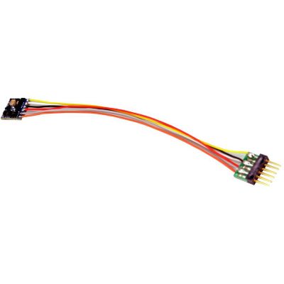
Compact direct decoder for small locomotives.
View Product →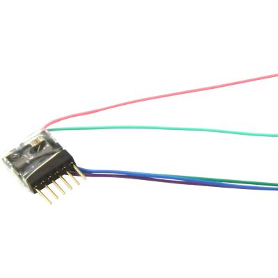
Very small multiprotocol version.
View Product →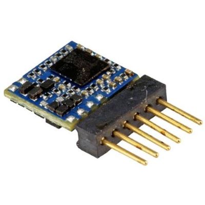
DCC-only version with a straight row of pins.
View Product →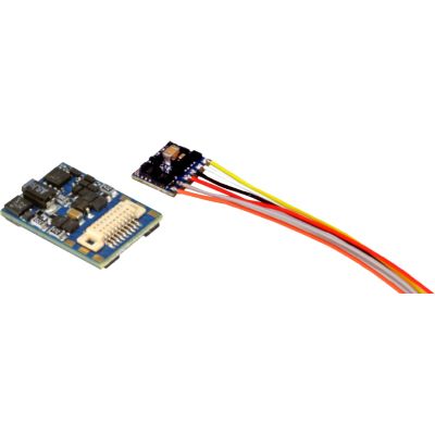
Angled DCC version for a short installation space.
View Product →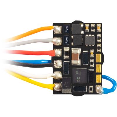
Extremely small version for restricted installation spaces.
View Product →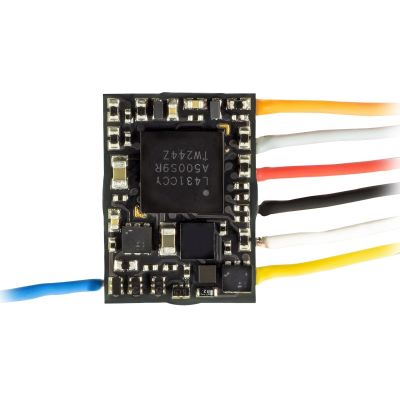
Compact driving decoder with a low profile.
View Product →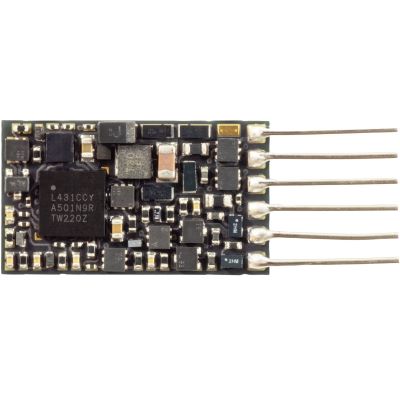
Single-sided version with a height of 1.6 mm.
View Product →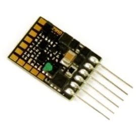
Compact version with several function outputs.
View Product →Flexible decoders for offset installation and different vehicle circuit boards.
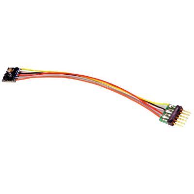
Flexible DCC version for offset installation.
View Product →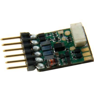
DCC and Motorola decoder for compact vehicles.
View Product →
Version supporting DCC, Motorola and Selectrix.
View Product →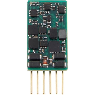
Plug-in decoder for suitable TT locomotives.
View Product →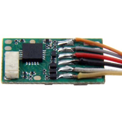
Flexible version for offset installation locations.
View Product →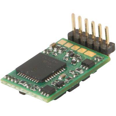
Angled version for short installation spaces.
View Product →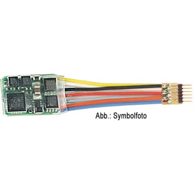
RailCom-capable decoder with a short cable run.
View Product →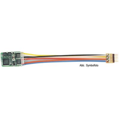
For decoder locations further away from the socket.
View Product →Additional versions for DCC, coach functions and compact sound conversions.
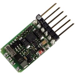
Compact DCC decoder for small locomotive models.
View Product →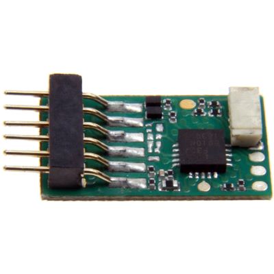
For lighting and auxiliary functions without motor control.
View Product →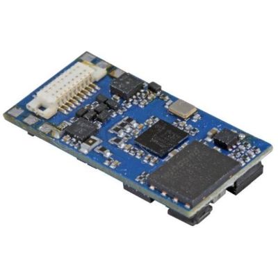
Multiprotocol sound decoder for compact vehicles.
View Product →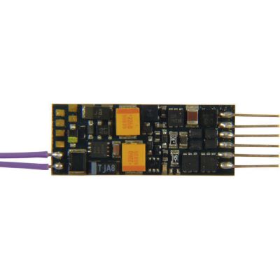
Compact sound decoder with SUSI and feedback.
View Product →NEM 651 describes a six-pin electrical vehicle interface with all contacts arranged in one row.
No. The design, pin orientation, motor current, dimensions and digital protocol must also suit the vehicle.
Contact 1 is often identified by an arrow, dot, number or the orange motor wire.
With some sockets, yes. The decoder must therefore only be inserted after the installation direction has been identified clearly.
The basic six-pin connector does not have a contact for the common positive lighting return.
This is possible with decoders that have additional solder pads or wires, provided the output and connected load are compatible.
A direct decoder saves space and wiring. A wired version can be positioned more flexibly inside the vehicle.
Angled pins are useful when there is no space behind the socket and the decoder board must lie above or beside the vehicle circuit board.
Yes, when sufficient additional space is available for the loudspeaker, sound enclosure and wiring.
No. Next18 uses a different connector and has significantly more contacts.
The continuous-current rating of the specific decoder is decisive. The locomotive current should be measured under load.
Professional installation is advisable when the pin position is unknown, the socket is damaged, very little space is available, the motor is old or a demanding sound conversion is planned.
The pin assignment, pitch, contact dimensions and installation space are based on the NEM 651 recommendation, 2017 edition. View the Standard Sheet
Content status: 17 July 2026. Check the current vehicle and decoder instructions before installation.
The main guide covers locomotive decoders, sound decoders, digital command stations, protocols, digitisation and layout planning.