1
The Command Station Sends DCC Packets
Speed, direction and function commands are transmitted as digital data packets through the booster to the track.




With standard DCC, the digital command station sends commands to the decoder. RailCom adds the return path: a compatible decoder can report its address, certain configuration values or other information back to detectors and control devices.
RailCom is a feedback technology used within the DCC digital format. A conventional digital command station sends driving and switching commands through the track to the decoder. RailCom allows a compatible decoder to transmit information in the opposite direction as well.
Depending on the decoder, command station, detector and software, the system can evaluate a locomotive address, certain CV values or status information. It can therefore determine more than whether a track is occupied. With local RailCom detectors, the system can also identify which feedback-capable vehicle is located in a monitored section.
RailCom does not replace a digital decoder or conventional track-occupancy detection. It extends DCC by adding a return channel. Several components must work together for a complete application: the decoder, RailCom cutout, detector, command station or interface and a suitable display or control program.
On a small layout, you can usually see immediately where a locomotive is. This information is considerably more important in staging yards, block sections and automated routes. Control software can assign a locomotive address to a section and therefore manage train positions more accurately.
A conventional current sensor only reports whether a section is drawing power. A local RailCom detector can additionally evaluate the transmitted decoder address. Vehicles without RailCom can still be detected as occupying the section through normal current measurement.
The feedback method is intended for the DCC data format. Motorola, mfx and Selectrix have their own technical characteristics and should not be confused with RailCom.
DCC provides the driving command. During brief pauses in the track signal, RailCom creates a return path from the decoder to the detector.
During normal operation, the decoder receives DCC commands. A very brief transmission window is created in the track signal for the response.
Speed, direction and function commands are transmitted as digital data packets through the booster to the track.
A brief pause in the signal is created after suitable DCC packets. This time window is known as the RailCom cutout.
During the cutout, the RailCom-capable decoder generates defined current pulses representing its feedback information.
A global or local detector converts the electrical signals into usable data.
The received information is assigned to a locomotive or a monitored track section.
The locomotive address, CV value or position can be displayed and used for automated operating sequences.
The feedback window is divided into two sections. The first channel is used primarily for basic identification information. The second channel allows more extensive data transmission. The data that becomes available depends on the complete system combination.
Both types of detector read feedback data, but they answer different questions. Local detectors are required for precise train positioning.
It monitors a larger power district and can, for example, evaluate feedback when programming on the main track.
It is assigned to a specific track section. This allows a returned locomotive address to be associated with a physical location.
It additionally reports occupancy caused by electrical consumers. Coaches and decoders without RailCom therefore remain detectable.
Local detectors make it easier to determine which train is standing in each storage siding.
Control programs can use addresses, sections and occupancy reports for train tracking and route protection.
RailCom-capable locomotives provide identification data. Other vehicles can still be detected through conventional current measurement.
RailCom provides the technical return communication. RailComPlus extends this with a convenient registration process for compatible DCC decoders.
| Designation | Main Purpose | Typical Benefit | Requirements |
|---|---|---|---|
| DCC | Transmits driving and function commands to the decoder. | Cross-manufacturer digital operation. | DCC command station and DCC decoder. |
| RailCom | Transmits data from the decoder back to the detector. | Identifying addresses, reading CV values and assigning train positions. | RailCom decoder, cutout and detector. |
| RailComPlus | Automatically registers compatible decoders. | Conveniently transfers locomotive names, addresses and function information. | RailComPlus decoder and compatible command station. |
| DCC-A | Standardised automatic registration process for DCC. | Identifies and addresses a decoder using a unique identifier. | DCC-A-compatible command station and decoder. |
| mfx | Independent protocol with automatic registration. | Convenient vehicle identification within the Märklin system. | mfx-compatible command station and decoder. |
A decoder can support RailCom without supporting RailComPlus. For automatic registration, both devices must be explicitly compatible with RailComPlus.
RailCom is not tied to a particular scale. The decisive factors are a compatible DCC decoder, sufficient installation space, the required motor current and a RailCom-capable digital system.
| Scale | Typical Use | Important Selection Criteria | Recommendation |
|---|---|---|---|
| Z scale | Specialist conversions using very small DCC decoders. | Dimensions, heat generation and low motor current. | Use only micro decoders explicitly designed for the application. |
| N scale | Compact RailCom and RailComPlus decoders. | Next18, NEM 651 and installation height. | Check LokPilot micro, Nano or comparable decoders. |
| TT scale | Drive and sound decoders with Next18 or PluX interfaces. | Interface, loudspeaker space and motor current. | Choose a compact decoder with RailCom enabled. |
| H0 scale | The widest selection of drive, sound and function decoders. | NEM 652, PluX22, 21MTC, AC/DC and function outputs. | Plan the command station and decoder together. |
| H0e and H0m | Narrow-gauge locomotives with compact DCC decoders. | Very limited installation space and reliable power pickup. | Compare micro decoders and energy-storage connections. |
| 0 scale | Sound, lighting, servos and digital couplers. | Motor output, loudspeaker and number of outputs. | Use powerful H0/0 or L decoders. |
| 1 and G scales | Large-scale railways with high currents and numerous functions. | Motor current, track voltage, screw terminals and booster output. | Plan for XL decoders and a suitable power supply. |
First check whether the vehicle decoder supports RailCom. On many decoders, feedback can be enabled or disabled using a CV. The exact setting is described in the relevant decoder instructions.
The digital command station or booster must then generate the RailCom cutout. Some devices already include a global detector. Additional local detectors are required to identify locomotives in individual track sections.
Divide each storage siding into suitable monitored sections. A feedback module such as a multi-channel RailCom detector can monitor several tracks and forward the identified addresses to the command station or control software.
Every power district needs a RailCom-compatible cutout. Unsuitable boosters can prevent feedback. On larger layouts, the command station, boosters, detectors and bus system should be selected as one coordinated concept.
Begin by building a short test section with a RailCom-equipped locomotive. Test address detection and CV reading before installing several modules beneath the layout.
Common causes include a missing cutout, disabled decoder feedback or an incorrect connection between the detector and command station.
Check whether the decoder supports RailCom and whether feedback is enabled in the CV settings.
Check whether the command station or booster actually generates a RailCom cutout and whether the detector is connected correctly.
Check the isolation points, feedback inputs and detector-channel assignments in the command station or software.
PoM reading requires a fully supported RailCom chain. Not every combination can display all CV data.
RailComPlus must be supported and enabled in both the decoder and command station. RailCom alone is not sufficient for automatic registration.
Check the track contacts, wiring, booster boundaries, detector load and possible interference caused by unsuitable electronics.
The selection is grouped by size and purpose. Before installation, always check the interface, dimensions, motor current, supported protocols and required function outputs.
Small locomotives require slim decoders, suitable interfaces and careful heat dissipation.
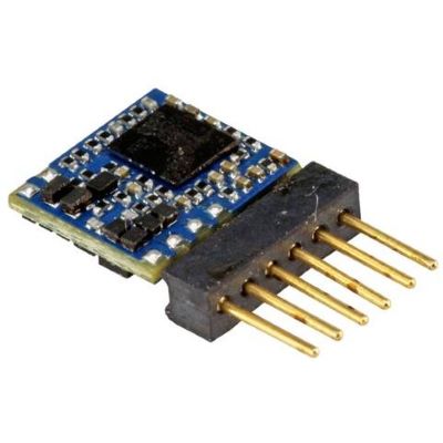
Compact DCC decoder with RailComPlus and a direct six-pin interface.
View Product →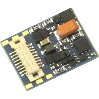
Slim Next18 decoder for modern locomotives and multiple units.
View Product →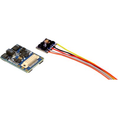
Angled direct decoder for particularly restricted installation spaces.
View Product →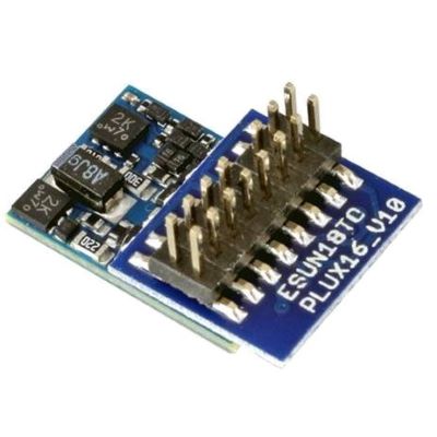
PluX16 version with six amplified function outputs.
View Product →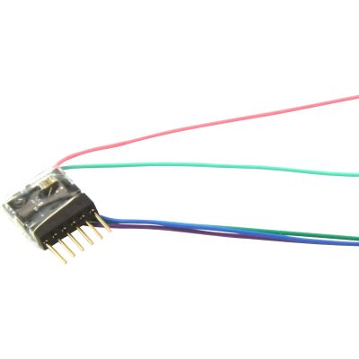
Small multi-protocol decoder with RailComPlus and six connection pins.
View Product →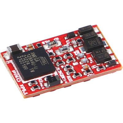
Multi-protocol decoder with self-adapting motor control.
View Product →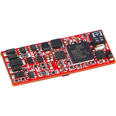
Unprogrammed Next18 sound decoder with advanced function mapping.
View Product →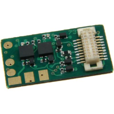
Compact decoder with RailComPlus and modern motor control.
View Product →Larger vehicles provide space for additional function outputs, sound, energy storage and more powerful motor output stages.
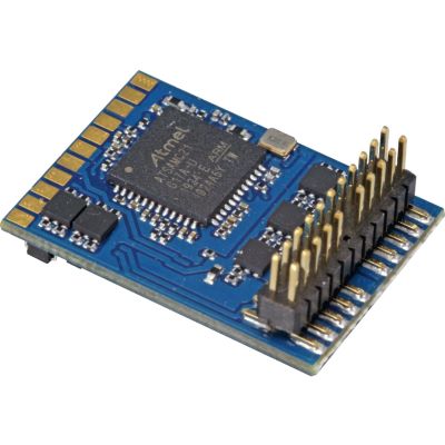
RailComPlus decoder with numerous amplified function outputs.
View Product →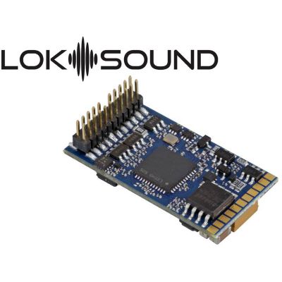
Multi-protocol sound decoder with ten simultaneously usable sound channels.
View Product →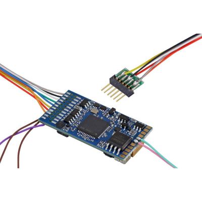
Sound decoder with loudspeaker, RailComPlus and broad protocol support.
View Product →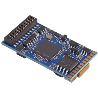
21MTC sound decoder with loudspeaker and automatic registration.
View Product →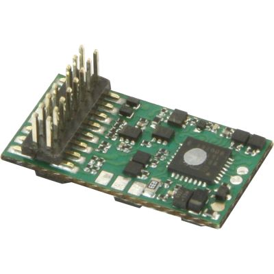
Updateable decoder with RailComPlus, ABC and function mapping.
View Product →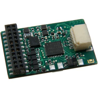
Multi-protocol decoder with RailComPlus and six function outputs.
View Product →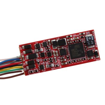
Unprogrammed sound decoder with RailComPlus and an eight-pin connection.
View Product →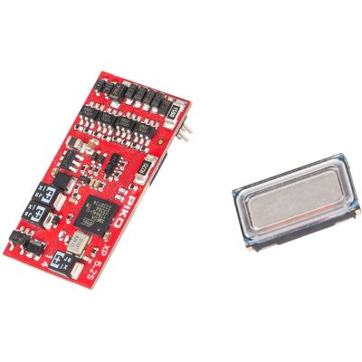
Vehicle-specific PluX22 sound decoder supplied with a loudspeaker.
View Product →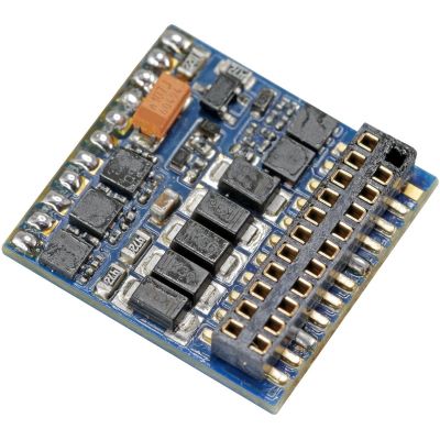
RailComPlus function decoder for driving trailers and additional lighting functions.
View Product →These components generate, receive or process RailCom data and provide the foundation for larger layouts.
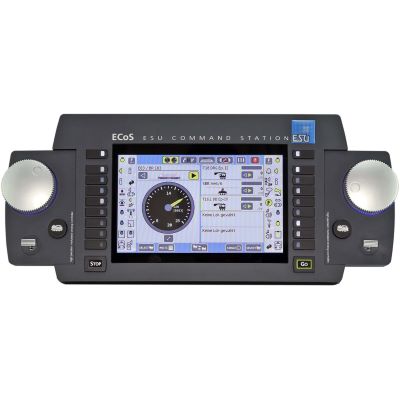
Touchscreen command station for DCC, RailCom, RailComPlus and other formats.
View Product →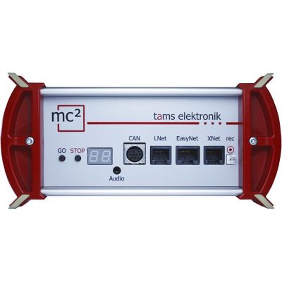
Modular command station with a RailCom cutout and global RailCom detector.
View Product →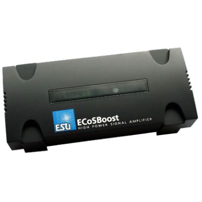
Powerful booster with RailCom feedback for additional layout sections.
View Product →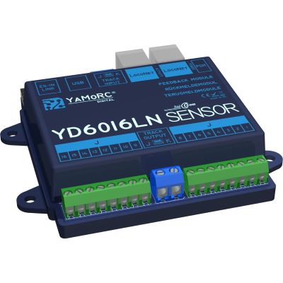
Feedback module with 16 local detectors and current sensors.
View Product →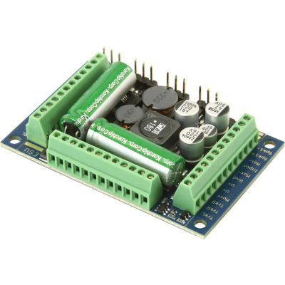
Powerful large-scale decoder with sound and RailComPlus.
View Product →The most important answers about feedback, the cutout, detectors, RailComPlus and compatibility.
Depending on the decoder and system, the locomotive address, CV values and other status information can be transmitted.
The cutout is a brief pause in the DCC track signal. During this window, the decoder can send its response to a detector.
Yes. A local detector can assign the returned address to the monitored track section.
No. DCC train operation also works without feedback. RailCom provides additional convenience for diagnostics, programming and automation.
No. Support must be stated explicitly in the technical specifications. On compatible decoders, the function may also need to be enabled.
A RailComPlus-compatible decoder can register automatically with a compatible command station and transmit locomotive and function information.
With a fully compatible combination of decoder, cutout, detector and command station, certain CV values can be read using Programming on Main.
RailCom can also be used on a centre-conductor layout with a DCC-capable command station and suitable DCC decoders. The track system and digital data format must be considered separately.
They can continue to operate digitally. A suitable current sensor can detect their occupancy but cannot read a RailCom address.
No. RailCom is the underlying feedback technology. RailComPlus adds an automatic registration process.
For more detailed technical information, see the NMRA specification for bidirectional DCC communication, the ESU information about RailComPlus and the relevant decoder and command-station instructions.
The central model railway guide covers scales, digital systems, layout planning, vehicles, track, scenery construction and maintenance.