
NEM 651: Understanding the 6-Pin Decoder Interface
What are the six contacts used for, where is pin 1 and which locomotive or sound decoder suits your locomotive? This guide explains the NEM 651 interface, its pin assignment, installation variants, gauges and limitations clearly and practically.
6 Contacts
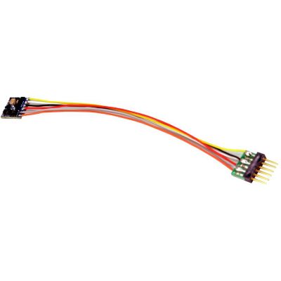
Compact interface based on the MOROP recommendation
What Does NEM 651 Mean?
NEM 651 describes a standardised six-pin electrical interface for model railway vehicles. It connects the main circuit board or wiring of a locomotive to a digital decoder. Through the six contacts, the decoder receives the track voltage, controls the motor and switches the direction-dependent front and rear lighting.
The connection was developed for small vehicles with limited installation space. It is particularly widespread in Gauge N and Gauge TT. Some older or especially compact H0, H0e and H0m models also have the single-row socket. Newer vehicle designs now frequently use Next18 or PluX because these interfaces provide more function contacts.
NEM 651 is not a digital protocol. The designation therefore does not indicate whether a decoder supports DCC, Motorola, Selectrix or several formats. In addition to being mechanically compatible, a decoder must suit the command station, motor current, installation space and required functions.
The current NEM 651 recommendation dates from 2017. It defines the electrical assignment, contact-pin dimensions, recommended decoder space and permitted contact load. The actual capacity of a particular decoder may be lower.








Pin 1 to pin 6
How Is the NEM 651 Interface Assigned?
The contacts are arranged in a straight row. Pin 1 must be clearly identifiable on the decoder and, where possible, in the vehicle. A mark, a bevelled circuit-board edge or the orange motor connection frequently indicates the correct side.
| Contact | Function | Standard Colour | Practical Meaning |
|---|---|---|---|
| 1 | Motor Connection 1 | Orange | Motor terminal for the defined forward direction |
| 2 | Motor Connection 2 | Grey | Second motor terminal, isolated from the track pickups |
| 3 | Right-Hand Track Pickup | Red | Electrical connection to the right-hand rail |
| 4 | Left-Hand Track Pickup / GND | Black | Electrical connection to the left-hand rail |
| 5 | Front Light | White | Switched output for the front headlight |
| 6 | Rear Light | Yellow | Switched output for the rear light |
Missing Common Positive
Why Does NEM 651 Not Have a Blue Contact?
The six standard contacts do not include a separate common positive conductor for lighting and auxiliary functions. Some decoders provide an additional blue wire outside the plug for this purpose. Without this wire, the lighting return path is provided by the vehicle circuitry. The wiring of the specific model therefore remains decisive.
Direct, wired or right-angled
Which NEM 651 Connector Types Are Available?
The electrical assignment remains the same, but the position and design of the plug may differ. Choosing the correct type determines whether the locomotive body can later be closed without placing pressure on the decoder.
Direct Plug
The six pins are attached directly to the decoder board. This version requires little space and is suitable for sockets with sufficient free length and height in front of them.
Plug with Wires
The decoder is connected to the plug by a short cable. It can therefore be positioned beside the socket, above the motor or in another free area inside the body.
Right-Angle Pins
After insertion, the decoder lies parallel to the locomotive circuit board. This version is required when there is very little space above the socket or the installation position is specified by the vehicle design.
How Much Space Does an NEM 651 Decoder Require?
The standard recommends an installation space of at least 20 × 10 × 4 millimetres for a standard decoder. For a sound decoder, at least 29 × 11 × 6 millimetres is specified. Additional space is required for the loudspeaker, sound enclosure and any extra wires.
Many modern micro decoders are smaller than this recommended space. Nevertheless, the plug, cable bend, insulation and body clearance must be considered in addition to the circuit-board dimensions. A decoder must not be trapped between the body and metal chassis.
From Z gauge to garden railways
Which Gauges Use NEM 651?
An interface does not belong exclusively to one nominal scale. The vehicle design, current consumption and installation space are decisive. Nevertheless, clear areas of application have developed.
| Gauge | Typical Use | Classification | Common Alternatives |
|---|---|---|---|
| Gauge Z | Only in individual vehicles with sufficient space. | Very Rare | Permanently wired micro and nano decoders |
| Gauge N | Many older and compact locomotives with a direct plug. | Main Application | Next18, E24, MTC14 or wired decoders |
| Gauge TT | Locomotives and multiple units from several vehicle generations. | Very Common | Next18, PluX12 and PluX16 |
| Gauge H0 | Compact or older two-rail vehicles with limited space. | Occasional | NEM 652, PluX22, 21MTC and Next18 |
| H0e and H0m | Narrow-gauge locomotives with small bodies and restricted decoder space. | Well Suited | Next18 or small wired decoders |
| Gauge 0 | Only with small motors and specially prepared circuit boards. | Unusual | More powerful H0 or Gauge 0 decoders |
| Gauges 1 and G | Generally unsuitable for the usual motor and function current. | Hardly Used | Large-scale, high-current and sound decoders |
Comparing six pins with other interfaces
Distinguishing NEM 651, NEM 652, Next18 and PluX
A larger number of contacts enables additional functions, but does not automatically make a decoder better. The socket fitted to the vehicle first determines which interface is mechanically suitable.
| Interface | Design | Typical Gauges | Capabilities | Special Feature |
|---|---|---|---|---|
| NEM 651 | Six pins in one row | N, TT, H0e and compact H0 | Motor and two lighting outputs | Very compact; installation orientation must be checked |
| NEM 652 | Eight-pin plug with wires | Mainly older H0 vehicles | Additional common positive conductor | Classic H0 interface |
| Next18 | Flat plug-in connection with 18 contacts | N, TT, narrow gauge and compact H0 | Several auxiliary functions; Next18-S for sound | Modern and very compact |
| PluX12 / PluX16 | Two-row pin header on the decoder | TT and H0 | More lighting and auxiliary functions | Reverse-polarity protection through a missing pin |
| 21MTC | Decoder socket fitted to vehicle-side pins | Mainly H0 | Numerous functions and sound | Check the standard and MKL versions |
More digital products are available in Decoders Without Sound , Sound Decoders and Decoder Accessories .
Insert the decoder and test it safely
Install an NEM 651 Decoder Correctly
Work only on a vehicle that is completely disconnected from the power supply. The operating instructions for the locomotive and decoder take precedence over general installation guidance.
Check the Interface
Make certain that the locomotive actually has a six-pin NEM 651 socket.
Determine the Motor Current
The decoder's permitted continuous rating must exceed the motor's actual current consumption.
Open the Body
Expose the body, wires and lighting boards carefully according to the manufacturer's instructions.
Remove the Blanking Plug
Pull the analogue plug out straight and retain it safely for a possible later conversion back to analogue operation.
Find Pin 1
Compare the marking, circuit-board label and orange motor side with the vehicle instructions.
Check the Connector Type
Determine whether a direct plug, wired plug or right-angle contacts are required.
Insert the Decoder
Guide all six pins into the socket simultaneously, straight and without sideways tilting.
Insulate the Decoder
Prevent contact with the metal chassis, flywheel, gearbox or exposed circuit-board tracks.
Use the Programming Track
Read the decoder first rather than immediately applying full track voltage.
Test the Motor
Check the direction of travel, slow-speed operation, noise and decoder temperature.
Check the Lights
The front and rear lights must match the direction of travel and must not flicker.
Close the Body
Position the wires and decoder so that no component is trapped when the body is fitted.
First Test After Installation
Switch Off Immediately in the Event of a Short Circuit, Smell or Severe Heating
If the locomotive does not move or both lamps illuminate unusually, do not repeatedly apply power to the decoder. Check the installation orientation, bent pins, motor insulation and possible contact with the metal chassis. Incorrect positioning can damage the decoder and vehicle circuit board.
Mechanically and electrically compatible
Which NEM 651 Decoder Fits My Locomotive?
Six Contacts Are Only the First Selection Criterion
First measure the free installation space and determine the required plug design. A directly attached plug is particularly compact, but it may collide with the locomotive body or a metal weight. A decoder with wires can be positioned more flexibly.
The motor current and digital format are the next considerations. A decoder rated at 0.5 A is sufficient for many N- and TT-gauge motors, but it must not be selected solely by gauge. Older motors, dirty gearboxes or mechanical blockages may draw considerably more current.
A DCC decoder is sufficient for a DCC-only layout. A multiprotocol decoder may be appropriate when different command stations or formats are used. RailCom, braking sections, SUSI, function mapping and energy-storage connections are additional features that are not defined by NEM 651 itself.
Sound is possible in principle. Because the six standard contacts include neither loudspeaker connections nor several additional function outputs, the loudspeaker and auxiliary wires are connected separately. In small vehicles, the available space is frequently the decisive limiting factor.
Selection by gauge and connector design
NEM 651 Decoders for N, TT, H0e, H0m and H0
On each product page, also check the dimensions, motor current, plug orientation, digital protocols and suitability for your specific vehicle. The gauge designation does not replace a technical check.
1:160 Scale and Compact Vehicles
Six-Pin Decoders for Gauge N
Low height and short circuit boards are particularly important in Gauge N. In addition to direct plugs, decoders with short wires are available for sockets that are difficult to reach or mounted at the side.
N and TT
ESU 59816 LokPilot 5 micro
Compact multiprotocol decoder with a directly attached six-pin plug.
View Product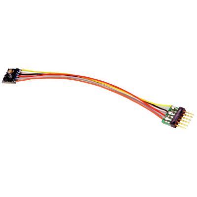
Wired Plug
ESU 59826 LokPilot 5 micro DCC
Micro decoder with a separate six-pin plug for flexible positioning.
View Product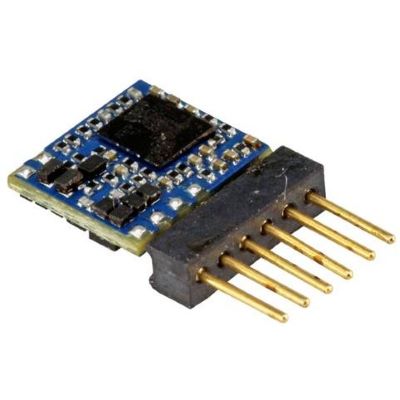
Direct DCC
ESU 59827 LokPilot 5 micro
Small DCC version for suitable vehicles with a direct plug position.
View Product
Gauge N
Lenz 10311-02 Silver mini
Compact locomotive receiver with a plug for suitable N-gauge vehicles.
View Product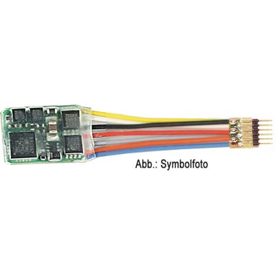
35 mm Wires
Fleischmann 685504
RailCom-capable decoder with a short cable between the board and plug.
View Product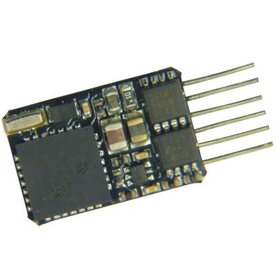
RailCom
Fleischmann 686101
Compact feedback-capable decoder for small N- and TT-gauge locomotives.
View Product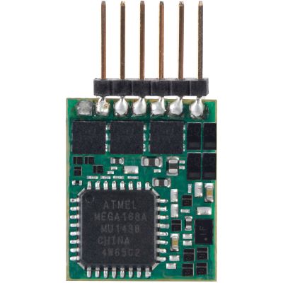
Multiprotocol
Viessmann 5297
Six-pin locomotive decoder with automatic detection of several operating modes.
View Product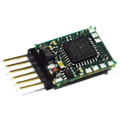
1:120 Scale and Compact Narrow-Gauge Models
NEM 651 Decoders for TT, H0e and H0m
Straight, angled and wired versions are particularly relevant in TT and narrow-gauge vehicles. In addition to the motor current, the orientation of the socket and decoder board must be checked.
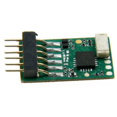
ID2 Micro
Uhlenbrock 73310
Small N- and TT-gauge decoder with protective functions and additional connections.
View Product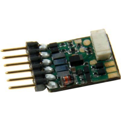
N to H0
Uhlenbrock 73416
Versatile mini decoder for N, TT, H0e, H0m and compact H0 models.
View Product
DCC and Motorola
Uhlenbrock 73415
Regulated multiprotocol decoder for DC and coreless motors.
View Product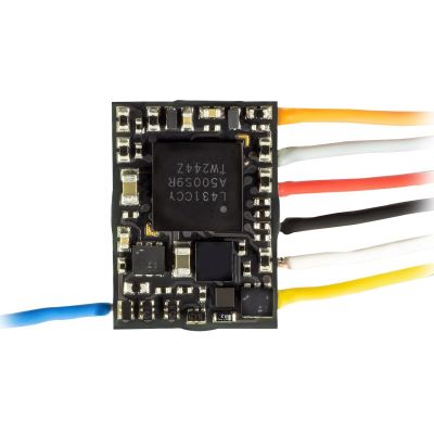
Very Compact
ZIMO MN150N
Particularly small direct decoder for confined N- and TT-gauge vehicles.
View Product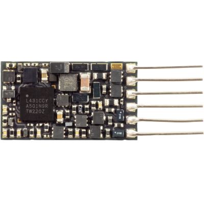
Low-Profile Design
ZIMO MN160N
Single-sided decoder with low height for difficult installation locations.
View Product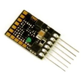
0.7 A
ZIMO MN170N
Miniature drive decoder with a direct plug and several function outputs.
View Product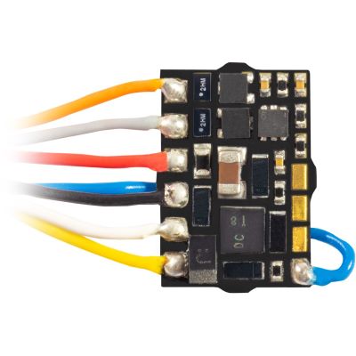
Subminiature
ZIMO MX615N
Small direct-plug solution for N- and TT-gauge locomotives with limited space.
View Product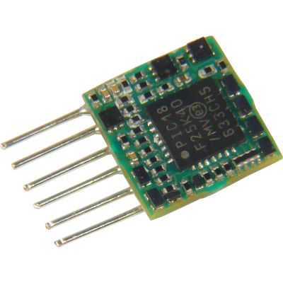
Direct Plug
ZIMO MX616N
Compact decoder for small locomotives with motor current up to 0.7 A.
View Product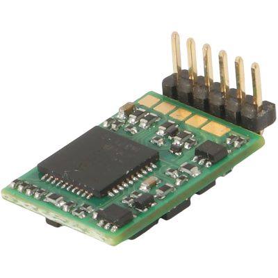
Right-Angle Plug
Roco 10887 MX617L
RailCom-capable decoder with angled pins for low-profile installation.
View Product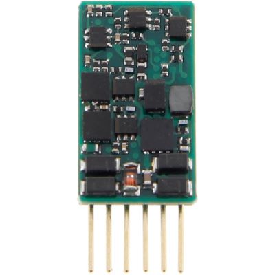
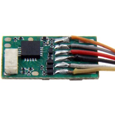
With Cable
Tillig 66033
Flexible decoder solution for vehicles with an inconveniently positioned socket.
View Product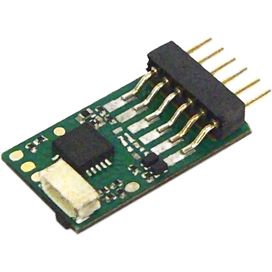
SmartDecoder
PIKO 46400
Multiprotocol-capable decoder for TT and other suitable vehicles.
View ProductCompact H0 Vehicles and Flexible Conversions
NEM 651 for H0 and Universal Applications
Some H0 models use the compact interface, although NEM 652, PluX22 and 21MTC are also widespread in this gauge. The motor output and installation space must be checked particularly carefully.
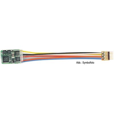
80 mm Wires
Fleischmann 685404
Flexible RailCom solution for H0e, TT, N and individual installation locations.
View Product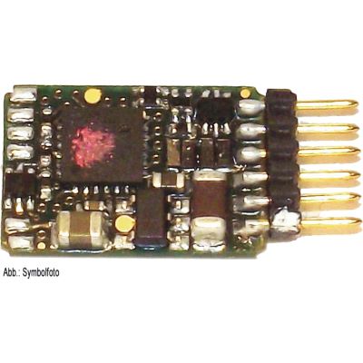
Straight Pins
Fleischmann 685305 MX617N
Compact RailCom decoder for H0e, TT and N with a direct plug position.
View Product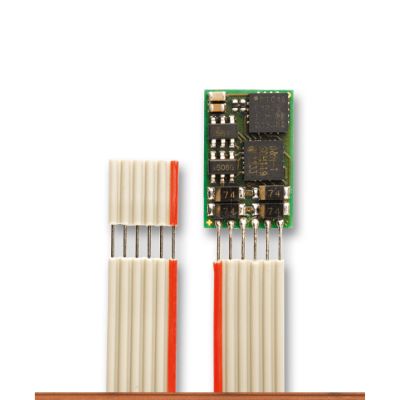
Ribbon Cable
Brawa 99802 DH10C-1
Multi-format vehicle decoder with SUSI and a flexible connection.
View ProductSound for Compact Locomotives
NEM 651 Sound Decoders
With sound decoders, the loudspeaker and any additional connections are located outside the six standard contacts. The decoder, loudspeaker and sound enclosure must fit into the available vehicle space together.
Micro Sound
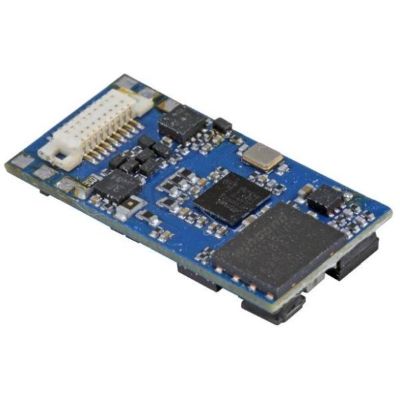
ESU 58816 LokSound 5 micro
Multiprotocol sound decoder with a six-pin connection for compact vehicles.
View Product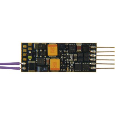
N and TT Sound
Fleischmann 687701
Feedback-capable miniature sound decoder for small locomotives.
View Product
Answers before purchase and installation
Frequently Asked Questions about the NEM 651 Interface
The information provided by the vehicle and decoder manufacturers remains binding when choosing a compatible product. The following answers provide general guidance.
What Does NEM 651 Mean on a Model Locomotive?
The locomotive has a six-pin interface for a suitable digital decoder. Track power, the motor and direction-dependent lighting are connected through the interface.
Is NEM 651 Always a DCC Connection?
No. NEM 651 describes only the plug and contact assignment. The decoder may support DCC, Selectrix, Motorola or several digital formats.
How Do I Identify Pin 1 of the NEM 651 Socket?
Pin 1 is frequently identified by a marking on the decoder or vehicle circuit board. On a wired version, the orange motor connection corresponds to pin 1.
Can I Insert the Six-Pin Decoder the Wrong Way Round?
This is mechanically possible with some sockets. The installation orientation must therefore be checked clearly before inserting the decoder.
Why Does the Locomotive Run Backwards After Installation?
The decoder may have been inserted in the wrong orientation, or the vehicle's motor connections may be reversed. Check pin 1 and the manufacturer's wiring diagram before changing any settings.
Why Does the Headlight Not Work Correctly?
Check pins 5 and 6, the common lighting return and the function mapping. Some vehicles have their own diode circuit for analogue operation.
Can an Analogue NEM 651 Locomotive Be Digitised?
Yes. The existing blanking plug is removed and replaced with a suitable decoder. The motor current, installation space and pin 1 position must be checked first.
Can I Return to Analogue Operation Later?
Many decoders support analogue direct-current operation. Alternatively, the original blanking plug may be reinstalled if it is undamaged and intended for that specific vehicle.
Does NEM 651 Support Additional Lighting Functions?
The six standard contacts include only the front and rear lights. Individual decoders may provide further outputs through separate wires or solder pads.
Is an NEM 651 Sound Decoder Possible?
Yes. However, the loudspeaker and additional connections are outside the six standard contacts. The available space for the decoder, loudspeaker and sound enclosure is particularly critical.
Can NEM 651 Be Replaced by Next18?
Not directly. The plug shape and contact assignment differ. A conversion requires a suitable adapter solution or a new vehicle circuit board and must be checked electrically.
What Motor Output May an NEM 651 Decoder Control?
There is no single value that applies to every decoder. The standard specifies a load rating for the individual plug contacts, while the permitted motor load is stated in the decoder's product description.
Use the technology reliably over the long term
Maintain, Program and Protect NEM 651 Decoders
A correctly installed decoder normally requires no mechanical maintenance. Clean track, well-maintained current pickups and a freely moving gearbox reduce current peaks and improve running characteristics. A stiff motor can overload even a decoder with an otherwise sufficient rating.
After installation, the locomotive address, acceleration and braking delay, maximum speed and lighting functions can be programmed. Extensive changes should be made one step at a time. Record changed CV values so that a working configuration can be reproduced later.
Further introductory information is available in the guides to Digital Model Railways , Locomotive Decoders and Digital Modules and Digitising Model Railway Vehicles .
More Knowledge about Decoders, Digital Technology and Model Railways
Discover further guides covering interfaces, digital command stations, protocols, gauges, layout planning, vehicles and technical model railway accessories.