Control
A handheld controller, display, app or computer creates the operator command.

With a digital model railway, several locomotives can be controlled independently on the same track. Lights, sound, couplers, turnouts, signals and routes can be switched individually. This guide explains command stations, decoders, DCC, mfx, feedback, boosters and the right way to get started in H0, TT, N, Z, 0, 1 and G.







On a digital model railway, the track does not only carry the electrical power for the motor. The digital command station also transmits control commands. Every digital railcar and locomotive has a decoder with its own address. The decoder recognises the commands intended for it and controls the motor, lighting, sound and other functions.
Several locomotives can therefore stand on the same electrically connected track while still operating independently. One locomotive can perform shunting movements, a second can wait with its lights switched on and a third can haul a train along the main line. This is the key difference from conventional analogue control, where the track voltage directly determines the speed of all vehicles within the respective electrical section.
Digital does not automatically mean fully automated. A small layout can be operated entirely by hand using a digital controller. Automatic routes, block operation, staging-yard control and computer operation only become possible when additional feedback modules, accessory decoders and suitable software are added.
To get started, you need at least a digital command station, a suitable controller, a power supply and a locomotive equipped with a compatible digital decoder. A coordinated digital starter set offers a particularly straightforward introduction.
A handheld controller, display, app or computer creates the operator command.
The command station converts the input into digital commands.
Power and control information travel together to the vehicle.
The decoder reads the address, speed and function commands.
The motor, lights, sound or coupler respond individually.
Occupancy detectors and decoders can return information.
Both control methods can provide lasting enjoyment. Digital technology is particularly worthwhile when several locomotives, individually switchable functions, sound or later automation are desired.
| Feature | Analogue Control | Digital Control | Practical Significance |
|---|---|---|---|
| Locomotive control | Via the voltage in the track section | Via individual decoder addresses | Several locomotives can move independently on the same track. |
| Lighting | Often dependent on track voltage and direction | Usually switched on and off separately | The lights can remain switched on while the vehicle is stationary. |
| Sound | Only limited or available through special solutions | Many sounds can be selected individually | Engine, horn, braking and announcement sounds are triggered individually. |
| Wiring | Several switchable electrical sections are common | Initial operation is possible with continuously powered track | The basic wiring can be easier to understand. |
| Turnouts and signals | Push buttons, control panels or relays | Accessory decoders, command station, app or computer | Routes and clear graphical control interfaces become possible. |
| Expandability | Well suited to manageable, manually operated layouts | Expandable from handheld control to automation | The system can grow with the layout step by step. |
Not every layout needs every component from the outset. The command station and locomotive decoder provide the foundation. Boosters, feedback modules and accessory decoders can be added as the requirements for power, convenience or automation grow.
This is the control centre of the layout. It manages addresses, generates the digital signal and connects controllers, networks, feedback modules and other devices.
The locomotive decoder controls the motor and lighting. A sound decoder adds a loudspeaker, driving sounds and selectable sound functions.
It controls functions without a traction motor, such as interior lighting, tail lights, driving trailers, maintenance vehicles or stationary lighting.
Turnouts, signals, uncouplers and other magnetic accessories receive a digital address and can be operated through the command station or as part of a route.
Feedback modules inform the command station or control software whether a track section is occupied or a contact has been triggered. This is essential for automatic operation.
A booster amplifies the digital signal and supplies an individual layout section with additional power. It becomes relevant on larger layouts or when many trains are operating simultaneously.
The digital protocol determines how commands are transmitted. The command station and decoder must support at least one common language. Multi-protocol devices support several formats.
| Term | Function | Typical Use | Important Before Buying |
|---|---|---|---|
| DCC | Standardised protocol for locomotive and accessory commands | Especially widespread on two-rail layouts, but not limited to them | The command station and decoder must both support DCC. |
| mfx | Bidirectional Märklin protocol with convenient vehicle registration | Primarily used with the Märklin centre-conductor system | Automatic registration requires a compatible command station and decoder. |
| Motorola | Older Märklin digital format | Existing vehicles and older Märklin digital layouts | Check the functions and address range of older decoders. |
| Selectrix | Digital format for driving, switching and feedback | Historically common with smaller scales and existing older systems | Not every modern command station supports Selectrix. |
| RailCom | Feedback method used within compatible DCC systems | Locomotive identification, address reporting and status information | The decoder, command station and feedback components must be compatible. |
| Multi-protocol | Supports several digital languages within one device | Mixed vehicle fleets and flexible layout concepts | The interface, current system and available functions must still be checked individually. |
The basic principle is similar for every gauge. The main differences involve the available installation space, the required current and the track and electrical system being used.
| Gauge | Typical System | Common Interfaces | Special Considerations |
|---|---|---|---|
| Z | Usually two-rail; digital conversion depends on the model | Compact specialist decoders or direct installation | Very limited installation space; consider current consumption and heat development. |
| N | Predominantly two-rail with DCC | Next18, NEM 651 and vehicle-specific circuit boards | Small decoders and careful cable routing are required. |
| TT | Predominantly two-rail with DCC | Next18, PluX12, PluX16 and NEM 651 | A good balance between installation space and compact vehicle size. |
| H0 DC | Two-rail, frequently DCC or multi-protocol | NEM 652, PluX16, PluX22, 21MTC and Next18 | A very wide selection of command stations, decoders and sound solutions. |
| H0 AC | Centre-conductor, frequently mfx, Motorola and DCC | 21MTC, PluX22 and manufacturer-specific circuit boards | The pickup shoe, wheelsets and vehicle version must suit the centre-conductor system. |
| 0 and 1 | DCC or multi-protocol | Large-scale decoders, screw terminals and powerful sound decoders | Allow for higher motor current and more powerful loudspeakers. |
| G | High-performance DCC and garden railway systems | Large-scale and vehicle-specific decoders | High current demand, long cables and outdoor operation require suitable components. |
A clearly planned setup helps to prevent unsuitable purchases. Define the track system and digital format first, then expand the layout in manageable stages.
Check whether the vehicles run on two-rail or centre-conductor track. This fundamental mechanical and electrical decision remains important during digital operation.
DCC is the natural basis for many two-rail layouts. Märklin users often look for mfx, Motorola and, where appropriate, additional DCC support.
Base the decision on the number of trains, the preferred operating method, power demand, feedback requirements, network features and planned future expansion.
Only open the vehicle in accordance with its instructions. The interface, decoder dimensions, motor current, loudspeaker space and required functions must all be compatible.
Begin with the address, direction of travel and lighting. Then configure acceleration and braking delay, maximum speed, function mapping and sound.
Once train operation is reliable, turnout decoders, signals, feedback modules, boosters or computer control can be added progressively.
Start by building a short, clearly arranged test circuit. Connect only the command station and one digital locomotive. Add further vehicles, turnouts and modules only after this combination operates reliably. This makes faults considerably easier to identify.
A digital system may consist of components from one manufacturer, but it does not have to be restricted to a single brand. The protocol, interface, bus connection and documented compatibility are the decisive factors.
Mobile Station, Central Station, mfx and modules for the H0 centre-conductor system.
Z21 command stations, Wi-Fi operation, feedback and compatible DCC components.
SmartControl, decoders, boosters and digital starter sets for several gauges.
ECoS, LokPilot, LokSound, SwitchPilot and comprehensive programming solutions.
Intellibox, handheld controllers, decoders and modules for versatile layout concepts.
DCC command stations, amplifiers, handheld controllers and locomotive decoders for two-rail layouts.
Compact locomotive and sound decoders for N, TT, H0 and larger gauges.
Modern DCC command stations, boosters, switching modules and feedback technology.
DiMAX control, wireless handheld controllers and high-performance technology for G scale.
Feedback modules, switching modules, signal control and layout accessories.
A digital starter set contains mutually compatible components. It is particularly suitable when no vehicles, track or digital command station are already available.
H0 · DCC
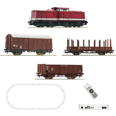
H0 train set with a digital Class 110 locomotive, freight wagons, track and z21start control.
View Starter Set →
H0 AC · mfx
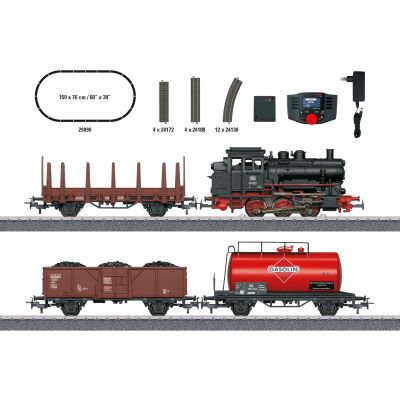
A digital introduction to the Märklin centre-conductor system with a steam locomotive and freight train.
View Starter Set →
H0 · WLAN
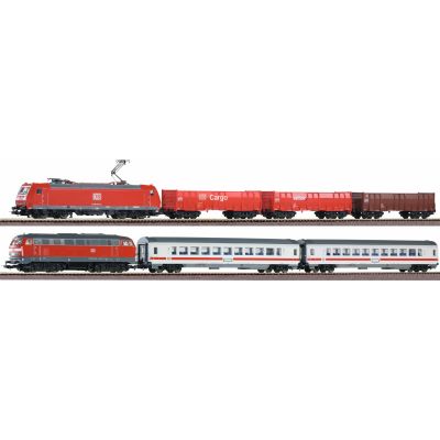
Comprehensive H0 starter package with two trains and wireless control.
View Starter Set →
H0 AC · Shunting
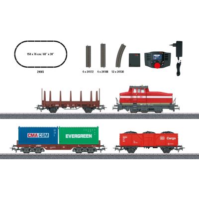
Compact digital H0 theme for freight yards, industry and shunting operations.
View Starter Set → TT · DCC
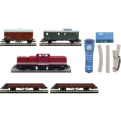
Digital TT starter set with a locomotive, wagons, track and controller.
View Starter Set → N · Digital
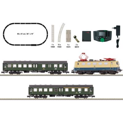
Space-saving digital introduction to N scale with a complete passenger train.
View Starter Set →Do not select a command station solely by its display. Supported protocols, output current, handheld controllers, feedback bus, network connectivity and expansion options are the decisive factors.
6 A · Multi-protocol
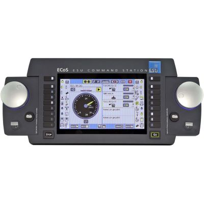
Powerful command station with a display, two speed controllers and comprehensive system management.
View Command Station →
Intellibox

Convenient command station for driving, switching and expanding existing digital layouts.
View Command Station →
mfx · DCC
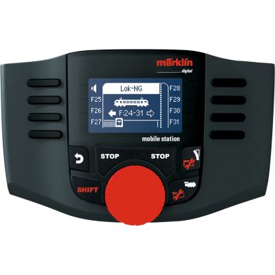
Compact handheld controller for locomotives and digital magnetic accessories.
View Handheld Controller →
CS3 plus
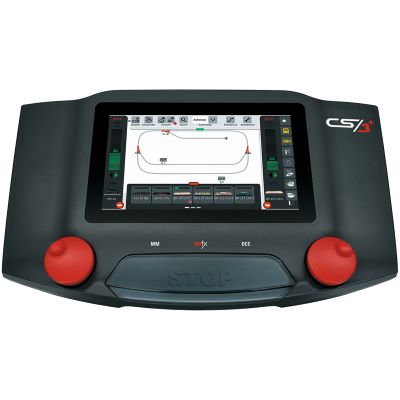
Comprehensive system command station for larger Märklin layouts and graphical control.
View Command Station →
Z21 · WLAN
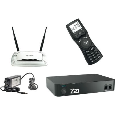
Network-enabled DCC control with a Wi-Fi router and compact handheld controller.
View Digital Set →
DCC · 5 A
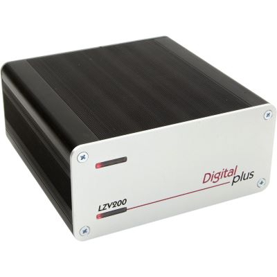
DCC command station with an integrated amplifier for powerful two-rail layouts.
View Command Station →
G · Wireless
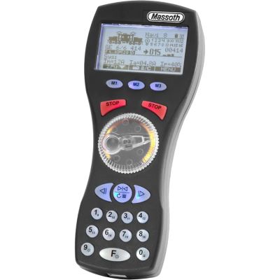
Wireless handheld controller for garden railway and DiMAX digital systems.
View Handheld Controller →
DCC · WLAN
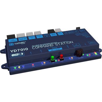
Modern DCC command station with network connectivity for flexible layout control.
View Command Station →The correct decoder must be mechanically and electrically compatible with the vehicle. Check the interface, dimensions, motor current, function outputs and supported digital protocols.
H0 · PluX22
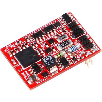
Multi-protocol decoder for compatible H0 vehicles with a PluX22 interface.
View Decoder →
H0 · NEM 652
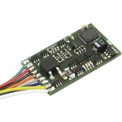
DCC locomotive decoder for many older H0 vehicles with an eight-pin interface.
View Decoder →
H0 · 21MTC
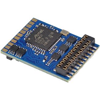
Multi-protocol decoder with a 21MTC connector for modern H0 vehicles.
View Decoder →
TT · PluX12
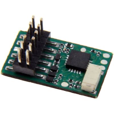
Compact decoder for suitable TT locomotives with a PluX12 interface.
View Decoder →
TT/N · Next18
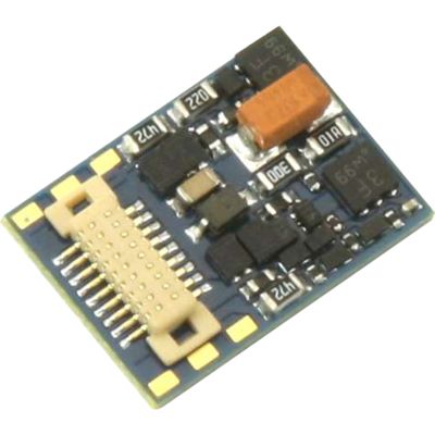
Compact multi-protocol solution for TT, N and small H0 vehicles.
View Decoder →
N/TT · PluX16
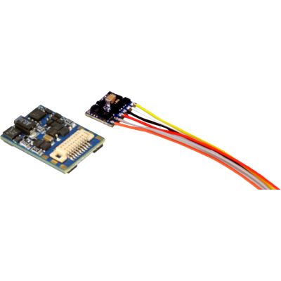
Small decoder for suitable vehicles with the compact PluX16 interface.
View Decoder →
N/TT · NEM 651
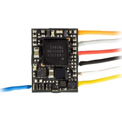
Extremely compact decoder for N and TT vehicles with a six-pin connector.
View Decoder →
0/1/G · Sound
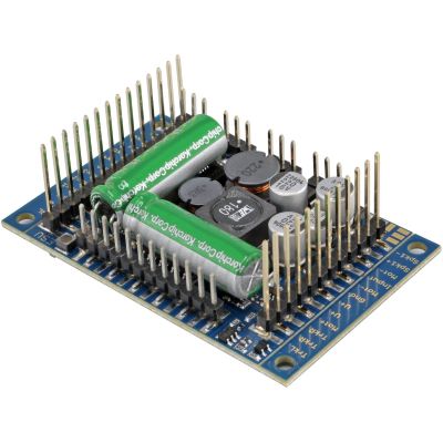
Powerful drive and sound decoder for large vehicles and high electrical loads.
View Sound Decoder →These components become relevant when the digital model railway grows beyond basic train operation. Check the digital bus, protocol and electrical capacity before making a selection.
Switching
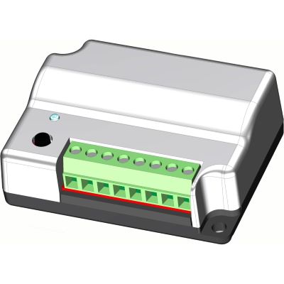
Accessory decoder for turnouts, signals and other magnetic accessories.
View Module →
S88N · Feedback
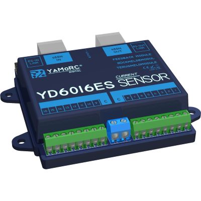
Sixteen feedback inputs for occupancy detection and automatic operating sequences.
View Feedback Module →
DCC/MM · OLED
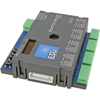
Eight-output accessory decoder for extensive turnout and switching tasks.
View Accessory Decoder →
Z21 · Booster
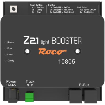
Additional power supply for a separate digital layout section.
View Booster →
Z21 · Feedback
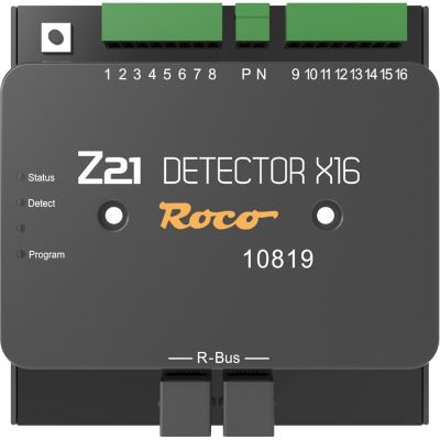
Feedback module for contacts, occupancy detection and automated train movements.
View Feedback Module →
m83 · Switching
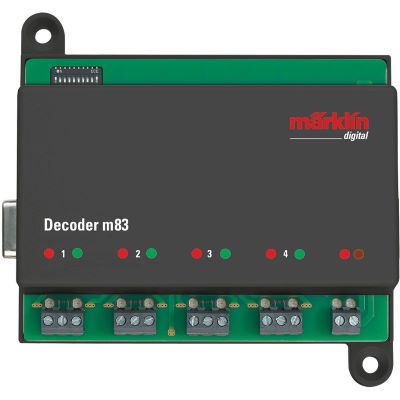
Digital decoder for switching turnouts and other magnetic accessories.
View Accessory Decoder →
3 A · Booster
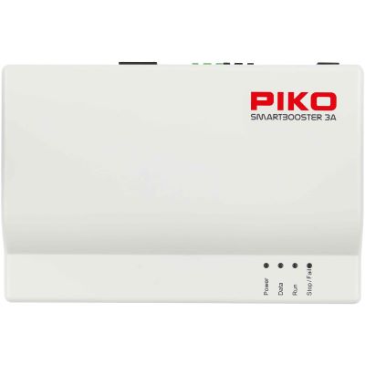
Power expansion for compatible PIKO SmartControl WLAN layouts.
View Booster →
3.5 A · Booster
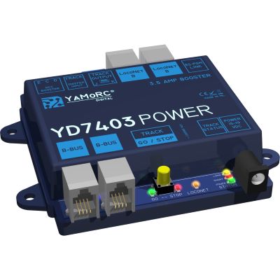
Universal booster for additional digital power and separate power districts.
View Booster →
Feedback
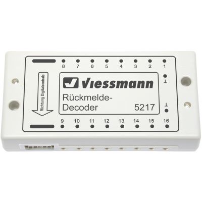
Feedback module for contacts, track occupancy and control tasks.
View Feedback Module →Many faults are not caused by a defective component, but by incompatible interfaces, duplicate addresses, dirty track or an overloaded power supply.
Two-rail or centre-conductor describes the track and current collection system. DCC, mfx or Motorola describes the digital language. These two levels must be checked separately.
Next18, PluX22, 21MTC, NEM 651 and NEM 652 are not interchangeable. The decoder dimensions and installation orientation must also be considered.
Several vehicles will then respond simultaneously. Assign unique addresses and record them in a vehicle list.
Illuminated coaches, sound locomotives and accessories all consume power. Divide larger layouts into power districts and add suitable boosters.
Not every system and motor is suitable for this. Follow the instructions for the command station and vehicle, and install a suitable decoder in the locomotive where necessary.
Test the system after adding each decoder, feedback module or booster. Step-by-step commissioning makes the cause of a fault considerably easier to find.
These answers summarise the most important decisions relating to command stations, decoders, protocols, apps and layout automation.
You need a digital command station with a power supply, a handheld controller or other user interface, track and at least one locomotive with a compatible digital decoder. A digital starter set already contains these basic components in a coordinated package.
Yes. Each locomotive is assigned its own decoder address. The digital command station sends the speed, direction and function commands specifically to the selected decoder.
No. DCC is a digital protocol and is not the same as the conventional term direct current. It is particularly common on two-rail layouts, but it can also be supported by suitable centre-conductor command stations and decoders.
Both transmit digital driving and function commands. DCC is a widely used cross-manufacturer standard. mfx is closely associated with the Märklin system and enables convenient automatic vehicle registration with compatible devices.
First check the existing interface, such as Next18, PluX22, 21MTC, NEM 651 or NEM 652. Then check the decoder dimensions, motor current, digital protocol, function outputs and, where applicable, the loudspeaker connection.
Many modern decoders support an analogue mode. The behaviour depends on the specific decoder and its settings, so check the instructions supplied with the vehicle or decoder.
Yes, provided the command station has a suitable network or Wi-Fi connection. Depending on the system, an additional router, Wi-Fi module or manufacturer-specific app may be required.
A booster is required when the power demand exceeds the output of the command station or when the layout is divided into separate power districts. Sound locomotives and illuminated trains increase the power demand.
An accessory decoder executes commands and operates equipment such as a turnout. A feedback module sends status information to the command station, such as whether a track section is occupied.
No. Digital operation can be entirely manual. Automatic routes and block operation additionally require feedback modules, suitable interface modules and control software.
This is often possible when the protocol, digital bus, interface and electrical specifications are compatible. A DCC decoder, for example, can be operated with different DCC command stations. Proprietary bus connections must be checked separately.
Straightforward handheld controllers and command stations from digital starter sets are often sufficient for small layouts. Easy operation, a suitable protocol and enough expansion options for the planned layout are important.
Discover more essential information about gauges, current systems, wiring, decoders, layout planning, maintenance and prototypical model railway operation.