PowerPack
The storage module connects to a designated decoder interface. On suitable systems, charging, discharge behaviour and maximum bridging time can be controlled by the decoder.

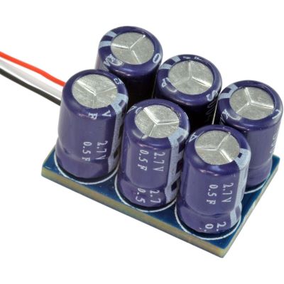
If a shunting locomotive stalls on a turnout, the headlights flicker or a sound decoder restarts after every brief loss of contact, a technically compatible buffer-storage module can significantly improve operational reliability.
PowerPack, Powercap, Stay Alive and USP systems store energy during normal operation and release it during brief contact interruptions. The goal is not simply the largest possible capacitance, but correct decoder compatibility, controlled charging, sufficient installation space and reliable stopping at signals.
A digital vehicle decoder requires a continuous electrical supply from the track. During slow running over dirty rails, short insulated frogs or in vehicles with only a small current-pickup base, contact can disappear briefly. An energy-storage module is designed to bridge exactly these short interruptions.
During normal track power, the storage module is charged in a controlled way. If track contact is interrupted, it can continue supplying the decoder, lighting, sound and, on suitable systems, the motor. The locomotive therefore runs more smoothly, lighting flickers less and the sound decoder does not need to restart after every brief contact gap.
Buffer storage is nevertheless not a substitute for model railway maintenance . Dirty wheels, bent pickup contacts, loose wires, a binding gearbox or poorly powered frogs must still be corrected. The module should bridge isolated interruptions rather than conceal permanently poor current collection.
The connection method is particularly important. Modern systems range from three-wire, decoder-controlled PowerPacks to Stay Alive controllers with their own electronics, Lenz USP systems and high-output large-scale Powercaps. Never assume that wire colours, solder pads or connection diagrams from one manufacturer apply to another decoder.
Without suitable current limitation, the decoder, rectifier, booster or digital command station can be unnecessarily loaded. Prefer explicitly approved PowerPack, Powercap, USP or Stay Alive solutions with a defined charging circuit. Bare supercapacitor arrangements also require the correct voltage rating, polarity, discharge path and, where capacitors are placed in series, suitable voltage balancing.
The storage module connects to a designated decoder interface. On suitable systems, charging, discharge behaviour and maximum bridging time can be controlled by the decoder.
Dedicated electronics combine supercapacitors with charging, protection and voltage conversion. Separate small capacitors can sometimes be positioned flexibly inside confined vehicles.
Compatible Lenz GOLD decoders can use POWER modules through dedicated connections and continue evaluating digital communication during brief contact interruptions.
High-output modules for Gauges 0, 1 and G must take account of larger motor currents, sound systems, gradients, smoke generators and heavier vehicles.
Interior lighting consumes far less power than a locomotive motor. A relatively small energy-storage module can therefore reduce visible flickering very effectively.
Replacement and vehicle-specific storage boards must only be used with the models for which they are explicitly intended. Match the vehicle and product number precisely.
A single electrolytic capacitor or supercapacitor requires the correct voltage rating, polarity, charging-current limitation and discharge path. Series-connected supercapacitors also require suitable voltage distribution or balancing.
Modern modules can buffer the decoder, motor and sound in a controlled way. Which parts of the vehicle are actually supplied depends on the exact module and decoder connection.
These calculations are theoretical planning aids. Intelligent PowerPacks can use voltage converters, cut-off thresholds, charging-current limitation and their own control electronics. The real bridging time must therefore always be tested on the completely assembled vehicle.
Approximation for a capacitor supplying an approximately constant current while its voltage falls.
Calculated from the entered values.
What theoretical capacitance would be required for a short desired bridging period?
Use only as a comparative planning value.
A shunting locomotive often needs only a short bridge across a contact gap. The goal is smooth passage over problematic track – not the longest possible running time without a digital track signal.
Check wheels, pickup shoes, contact springs, track and gearbox first.
Record manufacturer, product number, generation and firmware.
Use only the PowerPack or storage pads specified for the exact decoder.
Compare voltage, number of wires, charging circuit and storage module.
Keep clear of the motor, flywheel, cardan shaft, loudspeaker and body screws.
Make the vehicle electrically dead and discharge the storage module as specified before soldering.
Use flexible wires, reliable insulation and mechanical strain relief.
Read the locomotive address and a harmless CV with the module connected.
On controllable systems, begin with a short bridging period.
Test contact gaps, signals, braking sections, sound, lighting, short-circuit protection and analogue operation separately.
A simple storage module can allow a locomotive to continue moving into an intentionally dead section. Always test this with the storage module fully charged.
Some systems can limit the bridging time or react to the absence of the digital track signal. This can improve reproducible stopping at signals.
Compatible Lenz GOLD and POWER systems can continue evaluating digital communication during a genuine contact interruption. Use only the dedicated decoder connections specified for USP.
After installing storage, confirm that the decoder still detects the asymmetrical DCC braking signal reliably.
Retest DC and system-specific braking sections with the storage module fully charged.
Stored energy must not defeat or excessively delay the protective cut-off. After a derailment, the motor and wheels must stop reliably.
Manufacturer pages provide access to decoders, programmers and energy-storage products. The brand alone is not sufficient: the explicitly supported decoder generation and connection method remain decisive.
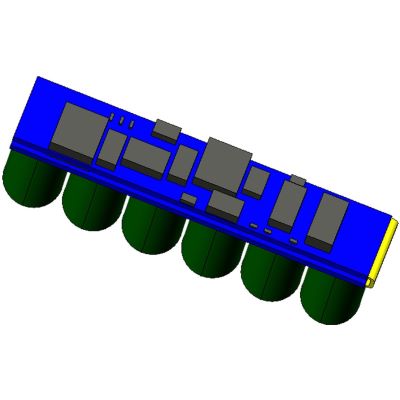
Compact microcontroller-controlled storage with 6 × 0.22 F for supported fifth-generation ESU decoders and vehicles with limited installation space.
View Product →
Higher-capacity storage for compatible LokPilot 5, LokSound 5 and supported LokPilot 5 Basic decoders, with controlled charging and adjustable bridging time.
View Product →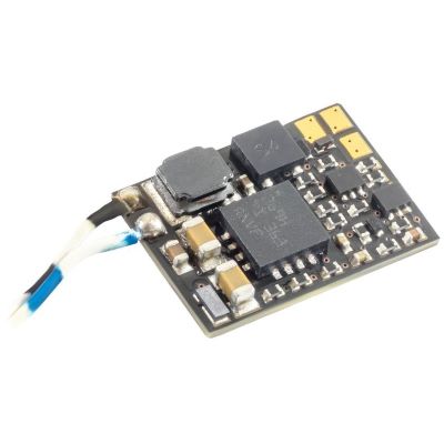
Compact controller supplied with three Mini Goldcaps that can be positioned conveniently in restricted installation spaces.
View Product →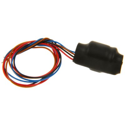
Storage solution with an integrated charging circuit. Compatible installations can remain programmable while the charging circuit limits start-up load.
View Product →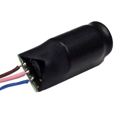
USP energy storage for explicitly compatible decoders in the Lenz GOLD system.
View Product →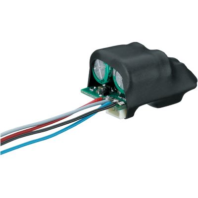
Buffer electronics with two 1 F capacitors and an integrated charging circuit for the explicitly specified Märklin mLD3 and mSD3 retrofit decoders.
View Product →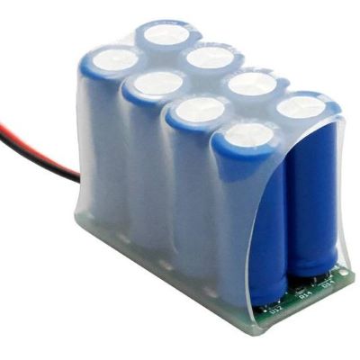
High-output garden-railway energy buffer with 230 watt seconds of storage for compatible Massoth digital projects.
View Product →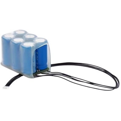
Specific storage solution for designated factory-fitted LGB mfx/DCC large-scale decoders.
View Product →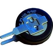
Coach-lighting solution with energy buffering to reduce visible flickering during short interruptions in current collection.
View Product →
Vehicle-specific spare part. Use it only when the product number and intended vehicle match exactly.
View Product →| Gauge World | Typical Storage Solution | Special Challenge |
|---|---|---|
| Z | nano controller / Mini Goldcaps | extremely restricted installation space |
| N | MiniXS / Stay Alive | small vehicle, heat and short current-pickup base |
| TT / TTe | compact modules | body height and decoder-board dimensions |
| H0 | PowerPack, Stay Alive, manufacturer-specific boards | match the exact decoder generation and vehicle circuit board |
| H0e / H0m / H0f | nano / distributed Goldcap solutions | very small vehicles despite 1:87 scale |
| 0 | high-output PowerPack / USP | motor, sound and auxiliary functions |
| 1 / G / IIm | Powercap 900 / 2300 / large-scale storage | high currents, smoke generators and heavy train loads |
The live search reads the current English buffer-storage category and relevant manufacturer pages. Every discovered product detail page is checked before display. Products with a recognised archive notice are excluded, small product images are normalised to the 400-pixel shop version and delivery or stock information is deliberately not displayed.
The current buffer-storage range will be checked when you approach this section.
Check the control wire, charging time, decoder compatibility, electrical contact and storage connection.
An incompatible or home-built storage circuit can affect reading and acknowledgement pulses. Check the connection and charging circuit.
Reduce the bridging time and retest the stopping section with the module fully charged.
The combined charging current of several vehicles can be excessive. Check the charging circuit and inrush-current limitation.
Check which decoder circuits are actually supplied through the selected storage connection.
Switch off immediately and check polarity, voltage rating, short circuits, charging circuitry and permitted load.
Real current consumption from the motor, lighting and sound can be much higher than the theoretical value used for planning.
Intelligent storage modules can have defined charging or start-up phases. Check whether this behaviour is normal or adjustable for the exact system.
After installation, do not test only one contact gap. Check slow-speed operation, motor control, sound start-up, lighting, programming, braking sections, signal stops, short-circuit protection and analogue operation. Buffer storage is properly integrated only when every relevant operating state works correctly.
No. The connection, voltage, charging circuit, control method and decoder generation must be compatible. Manufacturer approvals and the instructions for the exact decoder take priority over generic wiring examples.
An empty capacitor can draw a high current at power-up. Suitable current limitation protects the decoder, booster and digital command station from excessive charging current.
This is manufacturer- and decoder-specific. Wire colours and solder pads must be taken from the instructions for the exact decoder and storage module.
Many locomotive PowerPacks can buffer the decoder, motor, lighting and sound. Other connections and coach modules stabilise only particular parts of the vehicle.
The module may be bridging an intentionally dead stopping section. The bridging time, decoder-specific signal-stop behaviour and braking system must therefore be retested after installation.
As large as necessary and as small as practical. Installation space, vehicle current, required bridging time, charging behaviour and reliable stopping at signals determine the appropriate size.
Intelligent manufacturer-specific solutions frequently allow this. Home-built capacitor circuits can interfere with reading or decoder acknowledgement pulses.
Goldcap is a term used for a supercapacitor. A PowerPack is normally a complete system combining energy storage, charging electronics, voltage conversion and control.
It can bridge brief contact interruptions, but it does not replace cleaning the rails and wheels or repairing permanently poor current collection.
This can be possible with a suitable vehicle concept. The wiring, connector, current capacity and manufacturer approval must all support such an installation.
Possible causes include reversed polarity, overvoltage, a short circuit, unsuitable charging electronics or overload. Switch off track power immediately and inspect the installation.
Shunting locomotives, short vehicles with only a few current-collecting wheels and sound locomotives can benefit particularly during very slow running over problematic track.
The comprehensive Model Railway Guide covers decoders, digital command stations, electrical systems, maintenance, motor control, sound, track systems and many other topics.