Trigger
Function button F0 to Fxx, direction, sensor or another operating state supported by the decoder.

F0 controls the headlights, F1 the tail lights, F3 can activate both shunting mode and momentum override, F5 the cab lighting, F7 high beam and F8 perhaps a digital coupler: function mapping makes operation of a digital locomotive individual.
The Function Mapping Control Centre separates the function button, operating condition, logical action, physical AUX output and sound slot. Complex lighting, shunting and sound sequences can therefore be planned without blindly overwriting existing vehicle functions.
Function mapping determines which trigger starts a particular decoder action. The simplest example is: function button F1 switches AUX1. Modern decoders can do considerably more. F3 can, for example, activate shunting speed, disable acceleration and braking momentum and switch white shunting lights at both ends of the vehicle.
Several levels must therefore be considered separately. The function button is only the trigger. A logical function can be shunting mode, momentum override, sound fading or volume. A physical output is front light, rear light, AUX1 or AUX5. A sound slot may not require any electrical AUX output at all.
Operating conditions can then be added. An output may operate only in the forward direction, only in reverse, only while moving or only while stationary. Cab lighting, tail lights, shunting lights and digital couplers particularly benefit from these conditions. Some decoder families also allow several buttons or active functions to be combined logically.
Extensive mapping should therefore not be invented directly inside the decoder without a plan. A mapping table reveals duplicate assignments and shows which button should control which output, logical function and sound. The personal mapping planner on this page is designed for exactly that purpose.
Function button F0 to Fxx, direction, sensor or another operating state supported by the decoder.
Forward, reverse, stationary, moving or another logical requirement determines when the assignment is active.
Lighting, AUX, shunting mode, momentum override, sound slot, volume, coupler sequence or another decoder function.
Front light, rear light, AUX1 to AUXn or a connection on the vehicle circuit board.
Dimming, flashing, fading, a timed pulse or a special coupler or lighting sequence.
The assistant suggests a sensible structure for common functions. The matrix stores your own plan exclusively in the local browser. It does not change any CVs and does not write anything to a decoder.
Select the required function and decoder family.
Use a separate output for each cab, select a memorable function button and add direction plus stationary operation as conditions.
Each row describes one trigger and one action. Several rows using the same function button are explicitly allowed.
No mapping rows saved yet.
A shunting button can activate shunting mode, momentum override and two lighting outputs at the same time. Only an exactly duplicated row is marked as unnecessary duplication.
Conventional NMRA DCC mapping uses CV33 to CV46 for forward and reverse headlights and function inputs F1 to F12. Bit values determine which supported decoder outputs respond to each function input.
Modern decoder families can manage many more function buttons, outputs and operating conditions. Instead of calculating individual bit masks, complete mapping rows can combine trigger, condition and action.
Shunting mode, momentum override, sound fading or volume do not necessarily require a physical lighting output. They can still be assigned to a function button.
A single function button may trigger several mapping rows. F3 can therefore reduce speed, disable momentum and switch white shunting lights at both ends.
Depending on the decoder family, direction, speed, stationary operation, other active functions or further operating states can be used as logical conditions.
Horns, whistles, compressors, coupler sounds and other audio functions are assigned to sound slots or logical sound functions. Slot numbers depend on the loaded sound project.
The particular function button is only a suggestion. If a factory sound project already uses an established button layout, retaining that familiar arrangement can often be sensible.
Switch the front or rear lighting depending on direction. Keep the basic lighting function simple and predictable.
Control each end independently so that red tail lights can be switched off when the locomotive is hauling a train.
Combine shunting speed, momentum override and, where appropriate for the prototype, white lights at both ends.
Use a separate output for each cab, active only in the appropriate direction and preferably only while stationary.
Activate a second brightness level only when the normal headlights are already switched on.
Combine a time-limited output with an optional coupler sequence. Observe the permitted output load and activation time.
Assign the required sound slot to an easily reached button. After changing the sound project, check whether the slot assignment has changed.
A function decoder can control interior lighting, tail lights and destination displays independently of the locomotive.
Vehicle circuit boards, coupler sequences, sound logic, high-beam functions, cab-light logic and other manufacturer-specific features can require several mapping rows. Save the decoder project or all relevant settings before making changes.
Record the manufacturer, family, firmware and interface.
Save the original configuration or all relevant CV values.
Clearly identify front light, rear light, AUX outputs and logic levels.
Record the required functions in a matrix before programming.
Initially test exactly one button with one action.
Add forward and reverse conditions and test them separately.
Add shunting mode, momentum override, sound or further actions.
Configure dimming, timed pulses or lighting effects separately.
Test stationary operation, movement, both directions and several simultaneously active functions.
Update the locomotive card, command-station record and decoder project.
DCC provides common foundations, but extensive function mapping remains strongly manufacturer-specific. Original instructions and manufacturer programming software are therefore especially valuable for complex projects.
The number of available function buttons alone is not enough. The output type, interface, vehicle circuit board, digital protocol and mapping capabilities of the exact decoder family are what matter.
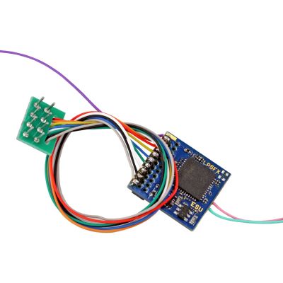
Multi-protocol function decoder without a motor output, offering flexible function-button assignment, lighting effects and extensive function outputs for suitable vehicles.
View Product →
PluX22 function decoder with ten amplified function outputs, two additional logic-level outputs and freely configurable function mapping.
View Product →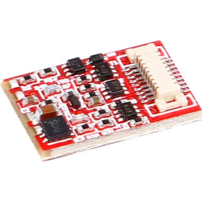
Compact function decoder with ten function outputs, including four logic-level outputs, and freely configurable functions up to F68.
View Product →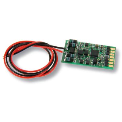
Six outputs with direction- and time-dependent switching, dimming, flashing, fade effects and function mapping up to F44.
View Product →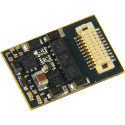
Compact locomotive decoder for small vehicles with function outputs and additional logic-level connections.
View Product →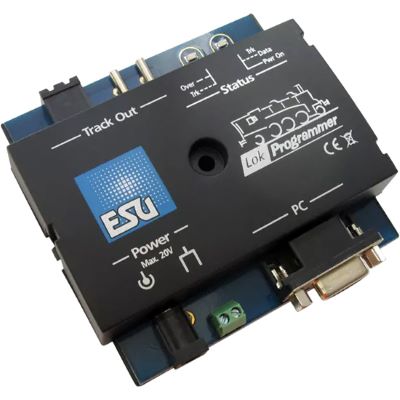
Edit and save buttons, outputs, operating conditions, sound functions and compatible ESU decoder projects graphically.
View Product →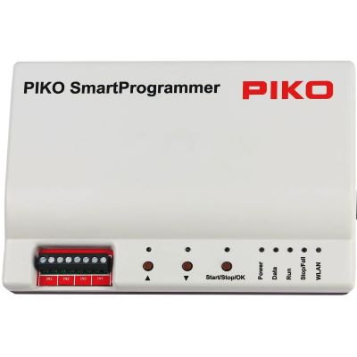
Configure compatible SmartDecoder functions and sound projects conveniently and test vehicle functions directly.
View Product →| Gauge World | Typical Decoders | Mapping Priority |
|---|---|---|
| Z | nano and micro decoders | few outputs, headlights and tail lights |
| N | Next18, NEM 651, Fx micro | compact lighting logic, multiple units and driving trailers |
| TT / TTe | Next18, PluX12, function decoders | tail lights, interior lighting and vehicle-specific circuit boards |
| H0 | NEM 652, 21MTC, PluX22, Next18 | lighting arrangements, sound, shunting mode and couplers |
| H0e / H0m / H0f | micro and wired decoders | compact lighting with restricted installation space |
| 0 | high-output and sound decoders | cab, engine room, servos and couplers |
| 1 / G / IIm | XL and large-scale decoders | smoke, pantographs, servos, sound and complex sequences |
Check whether the command station transmits the selected function button, whether a mapping row exists and whether the physical output works electrically.
A direction condition has probably been configured incorrectly. Test forward and reverse separately.
Several mapping rows may intentionally use the same button, or the vehicle circuit board may connect the two loads electrically.
The button and sound slot may not match the currently loaded sound project.
The stationary or direction condition may be missing or may be interpreted differently by the decoder family.
Shunting mode and lighting are separate actions. Both must be assigned to the same button or linked through a suitable logical condition.
The factory reset replaced the saved assignments. Reload the saved decoder project or rebuild the mapping.
The command station, handheld controller, decoder or selected digital protocol may not support the complete required function range.
Decoder terminology and vehicle circuit-board labels may differ. Check the interface pin assignment and vehicle documentation.
Product Radar searches current English decoder pages and relevant manufacturer ranges. Every discovered product detail page is checked before display. Products with a recognised archive notice are excluded, smaller product images are normalised to the 400-pixel shop version, and delivery or stock information is deliberately not displayed.
Live checking will begin when you approach this section.
A good button layout is not finished on the programming track. Shunting mode must work with the driving behaviour, cab lighting with direction and stationary operation, a digital coupler with a safe activation time and sound functions with the sound project actually loaded in the decoder.
Function mapping defines which trigger starts a decoder action. The action can be a physical AUX output, a logical decoder function or a sound slot.
No. F1 is a function button and AUX1 is a physical output. Mapping can connect them, but they are not inherently the same thing.
Yes. Modern decoders frequently allow several mapping actions for the same function button, for example shunting speed, momentum override and shunting lights.
Many advanced mapping systems allow this. The operating conditions should be chosen so that contradictory states are avoided.
CV33 to CV46 belong to conventional NMRA DCC function mapping. They map forward and reverse headlights and function inputs F1 to F12 to supported decoder output locations using bit masks.
Advanced mapping uses larger assignment tables and can combine more function buttons, operating conditions, physical outputs and logical decoder functions than the conventional CV scheme.
Ideally, each cab has a separate output. Direction of travel and stationary operation can additionally be used as conditions where supported by the decoder.
Depending on the decoder, one function button can activate shunting speed, momentum override and a suitable shunting-light arrangement at the same time.
With suitable sound decoders, yes. The available sound functions and slot assignments depend on the sound project currently loaded in the decoder.
The command station, handheld controller, decoder and selected digital protocol must all support the required function range.
Yes. A factory reset can replace custom assignments with the manufacturer's or sound project's default mapping. Save the decoder project before extensive changes.
Manufacturer-specific programming systems are particularly convenient for complex assignments, for example the ESU LokProgrammer for compatible ESU decoders or the PIKO SmartProgrammer for compatible SmartDecoders.
The comprehensive Model Railway Guide covers decoders, digital command stations, lighting outputs, motor control, sound, interfaces, electrical systems and many other topics.