Modellbahn Keks
Welcome!
Our cookies offer you a fast, relaxed and full-featured shopping experience. Some are necessary to operate the website and its functions. Others help us to improve our services. If you agree to this, simply consent to the use of cookies for preferences, statistics and marketing by clicking on "OK". Alternatively, you can deactivate individual cookies under "Customise cookies" or all cookies, except those required for the function of our website, under "Reject all".
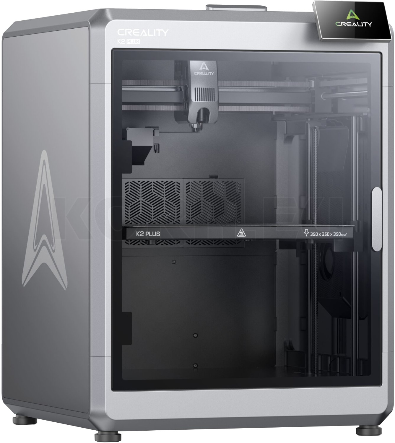
Creality K2 Plus 3D Printer for large model-making projects
Design large models thoughtfully

3D Printing for Gauge 0, Gauge 1 and Garden Railways

FDM suits large façades, platforms and robust model structures. Resin adds detailed figures and fittings. For garden use, material, drainage and mounting also matter: a large build volume alone does not make a durable outdoor model.

Choose the process to suit the part

Which projects benefit from a larger scale?

3D printing for Gauge 0, Gauge 1 and garden railways makes custom buildings, loads and accessories possible. Larger dimensions make some details easier but increase material use and print time. Plan construction and location together. A scenic accessory for an indoor layout faces different requirements from a garden railway façade exposed outdoors all year.

Typical applications and their key checks
Project Suggested construction Check before use
Façades and sheds Segmented FDM walls with separate windows and doors. Straightness, glued joints, roof overhang and access.
Platforms and loading ramps Repeatable modules with a load-bearing substructure. Height, vehicle clearance, mounting and drainage.
Bridges and retaining walls Printed cladding on a suitable supporting structure. Load transfer, supports, deflection and maintenance access.
Figures, machinery and loads FDM for robust shapes, resin for particularly fine surface detail. Weight, centre of gravity, fragile fittings and material suitability.
Functional brackets and covers FDM parts reinforced where needed, with accessible screws. Layer orientation, sustained loads, temperature and water ingress.

A shed, crate or short section of ramp cladding makes a manageable first project. A load-bearing bridge or precision drive requires additional calculation and testing. Start with a representative joint before printing all the parts.

Distinguish track gauge from model size

Scale correctly for Gauge 0, Gauge 1 and IIm

Under NEM 010, Gauge 0 is usually listed as 1:45 with a standard-gauge track width of 32 millimetres; 1:43.5 is also used in some regions. Gauge 1 uses 1:32 on 45 mm track. IIm represents metre gauge at 1:22.5, also on 45 mm track. The same track gauge therefore does not mean the same vehicle or building size.

One full-size metre becomes approximately 22.22 millimetres at 1:45, exactly 31.25 millimetres at 1:32 and approximately 44.44 millimetres at 1:22.5. A shed six metres long therefore becomes about 133.33, 187.5 or 266.67 millimetres long. Always check the scale explicitly stated for a file.

An H0 file at 1:87 is enlarged to approximately 193.33 per cent for 1:45, 271.875 per cent for 1:32 and approximately 386.67 per cent for 1:22.5. Redesign wall thicknesses and screw holes afterwards instead of simply enlarging them without checking.

Indoor layout or outdoor location?

Use PLA, PETG, ASA and resin appropriately

Distinguish UV exposure, heat, moisture and mechanical loads. The material name alone does not describe the lifespan of a finished printed part. Manufacturer formulation, print quality, geometry and location affect the result. The following table provides an initial selection guide.

Choosing materials for large model railway parts
Material Suitable starting point Key limitation
PLA and PLA+ Decoration, prototypes and indoor building parts. Check heat resistance; not a general recommendation for outdoor models permanently exposed to sunlight.
PETG Robust housings, brackets and many large FDM parts. Check the specific filament's UV and temperature data; there is no unlimited weather-resistance guarantee.
ASA Outdoor parts where UV and weather resistance are particularly important. More demanding to print; provide a suitable enclosure for large parts and controlled ventilation.
Resin Figures, fittings and fine decorative parts. Check outdoor suitability, toughness and post-curing for the specific material; do not assume standard resin is weatherproof.

PETG is often a practical starting point for larger parts because it has a comparatively low tendency to warp. ASA offers useful properties for UV exposure but requires suitable printing conditions. With both materials, assess the adhesive, screw joints and coating too: the weakest element can limit usability.

Weather resistance starts with shape

Plan roof overhangs, drainage routes and clearance from permanently damp ground. Avoid inaccessible pockets where rainwater can collect. An apparently closed FDM print is not automatically watertight; seams and layer bonds may leak. A model building is therefore not a tested protective enclosure for electronics.

A suitable coating can offer extra protection but does not replace appropriate material selection. Test adhesion and compatibility on a spare piece. Inspect outdoor models regularly for cracks, loose joints and deformation. For seasonal layouts, removable parts make dry storage easier.

Keep large surfaces manageable

Use build volume and divide parts sensibly

The largest dimension is only the starting point

Check the planned print orientation, including supports, brim and clearance from the edge. A part 300 millimetres long does not automatically fit in every orientation within a nominally 300 mm build volume. Usable height and removal after printing must also be suitable.

A larger printer can reduce the number of joints. Splitting parts can still offer advantages: individual sections can be oriented more effectively, finished more easily and replaced separately if damaged. Place joints at building corners, pillars, downpipes or visible changes of material wherever possible.

Test joints before printing a complete wall

Locating pins, tongue-and-groove joints or tabs on the rear help alignment. Slicer cutting tools can add connectors; CAD design changes offer greater control. First print a short pair of mating sections in the intended material and orientation.

Allow assembly clearance and room for adhesive. Screws need sufficient material around the hole and accessible mating components. Threaded inserts or captive nuts can be useful, but must suit the wall thickness and loads. Tight press fits are no substitute for a well-designed joint.

Build strength through geometry

Ribs, perimeter frames and short unsupported spans stiffen large surfaces without making the whole body solid. Orient loaded parts so critical forces are less likely to pull layers apart. Check transitions between thin walls and substantial screw mounts particularly carefully.

For a bridge carrying trains, a suitable load-bearing substructure with printed façades and railings is a useful approach. One successful test run does not confirm lasting load capacity. Account for vehicle weight, deflection, temperature changes and ageing in the design.

Use print time effectively

Prepare layers, walls and filament

For large FDM building parts, a 0.4 mm nozzle with a layer height of approximately 0.16 to 0.24 millimetres can be a starting point. A compatible 0.6 mm nozzle with approximately 0.24 to 0.32 millimetres is worth comparing for coarser surfaces. These are our suggested starting ranges for test prints, not validated universal profiles.

Fine brick textures, gutters and lettering may require a smaller nozzle or separate parts. Check the generated toolpaths, rather than just the model preview. Wall thickness depends on line width and the actual arrangement of paths; nozzle diameter alone does not determine it.

Choose temperature, cooling and speed according to the specific material profile. Wider extrusion paths require greater melting capacity. A high advertised movement speed therefore says little about the print time for a detailed façade. Compare the slicer's estimate using the actual settings selected.

Plan drying and storage together

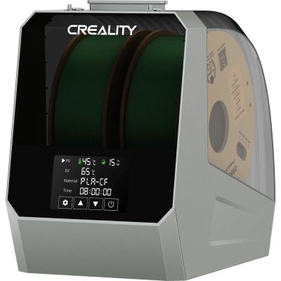
Moisture in filament can affect surface finish and layer adhesion. Store spools dry and check material condition if you notice unusual stringing or bubbles. A filament dryer must suit the recommended temperature, roll size and spool. Do not copy drying settings from another manufacturer without checking.

A sealed storage box with desiccant keeps dry material dry; it does not automatically replace active drying of a damp spool. In 3D accessories you will find equipment for different workflows.

A modular design for the layout

Plan a garden railway shed in 1:22.5

Our planning example uses full-size dimensions of six metres long, three metres wide and three metres to wall height. These become approximately 266.7 × 133.3 × 133.3 millimetres, with the roof added above. This is a design for test prints, not a documented practical test.

Prepare materials and tools

You need CAD software and a slicer, suitable filament, a compatible printer, callipers, a square and adhesive compatible with the material. Also allow for glazing film, a suitable baseboard and, if needed, screws and nuts. Choose the material for the finished shed's actual location.

1

Define walls and split points

For example, divide the long wall into two sections of approximately 133.35 millimetres. A covering pillar can conceal the joint. A wall thickness of about 2.4 millimetres is one possible design starting point; add ribs and check stiffness on a sample.

2

Print a corner as a sample

First make a wall section with a window, corner joint and mounting point. Check dimensional accuracy, the adhesive gap and the visible surface. Adjust the design before printing the entire building.

Test with the intended material

A PLA sample checks the shape but does not automatically confirm the fit of a later ASA or PETG print.

Keep a traceable record of the result

Record the file version, profile, material and measured deviations together with a photograph of the joint.

3

Keep the roof and floor accessible

Design a removable roof with an overhang and a suitable plinth. Keep drainage routes open and avoid enclosed water traps. A design that can be dismantled makes later cleaning, repairs and replacement of damaged windows easier.

4

Assemble and check at the intended location

Dry-fit the segments, glue according to the material instructions and allow the joint to cure fully. Check positioning and clearance from passing vehicles. For outdoor use, first observe a sample under local conditions.

In Gauge 1, the same shed would have a footprint of approximately 187.5 × 93.75 millimetres; in Gauge 0 at 1:45, approximately 133.33 × 66.67 millimetres. Reassess wall thicknesses and joints for each scale. Find further ideas in scratch-building buildings and designing platforms.

Limit material use and failed prints

For geometrically similar, fully solid scaled objects, volume increases with the cube of the linear scale factor. Doubling the length in every direction means eight times the volume. Hollow buildings with redesigned walls do not follow this simple calculation, so use the slicer's material estimate.

Compare a single-piece print with several segments, including supports and connectors. Multicolour printing adds purge material. Also allow for assembly, sanding, primer and rejected prints. The 3D printing cost calculator helps you compare options. For a few specialist parts, using a printing service may be economical.

Narrow down common faults systematically

  • Wall corners lift: check the build plate, first layer, material profile and draughts; divide large surfaces if needed.
  • Joints are too tight: correct dimensional accuracy, print orientation and assembly clearance on a short sample.
  • Brackets split between layers: investigate load direction, transitions, material condition and layer adhesion.
  • Outdoor parts warp: assess heat at the location, material data, sustained loads and mounting together.

Prepare for long print runs and later repairs

Before a large print job, check the estimated filament quantity, including supports and a reserve. Make sure the spool unwinds freely and material feeding works throughout the full range of movement. Watch the first layer particularly carefully. A small initial fault can become increasingly visible along a long wall.

Number segments on hidden surfaces and note their installation orientation. Keep print files for roofs, walls and fittings separately. You can then replace a single damaged component later. Particularly for series of buildings, a shared grid for windows, doors and connection points saves repeated adjustments.

Combine large structures with fine fittings

An FDM building can use separate resin fittings or ready-made railings. Choose mountings that protect fragile parts during transport. Check every material for the intended use. Resin requires cleaning and post-curing according to the manufacturer's instructions, plus the protective equipment specified in the safety data sheet. A carefully made FDM structure does not remove these steps for the added parts.

Explore the manufacturers' ranges

Compare printers, materials and accessories within each system.

Equipment for your large model railway projects

Find printers, filaments and resins

Search by product, material, colour or item number. Combine process, category and manufacturer filters. The list loads current products from the linked categories. Check printer compatibility and material properties on the product page.

The product list is being prepared. You can open the categories directly.

View all 3D tools

Frequently asked questions about large model railway prints

Do I need a large-format printer for a garden railway?

Not necessarily. Many buildings can be split into walls, roof and plinth. A larger build volume reduces joints but does not replace suitable design.

Is every PETG filament weatherproof?

A blanket guarantee would be too broad. Check the specific filament's data, location, loads and processing. Assess joints and coatings on the finished part too.

When does ASA make sense instead of PLA?

ASA is a useful candidate for outdoor parts exposed to UV. It requires suitable printing conditions and ventilation. PLA remains practical for many decorative indoor models and shape prototypes.

Are Gauge 1 and garden railways on 45 mm track the same size?

No. Gauge 1 uses 1:32, while IIm typically uses 1:22.5. The same track gauge does not guarantee matching buildings, figures or vehicle proportions.

Can I print an entire bridge that carries trains?

This is a demanding structural project. A suitable substructure with printed cladding is often easier to design reliably. Material, loads, layer orientation and ageing must all be considered.

Can a printed building stay outside in winter?

That depends on the material, design and location. Avoid standing water and check for damage. A removable structure allows dry storage if suitability has not been established.

Technical background: MOROP NEM 010, LGB on G scale and Prusa on PETG, ASA, splitting parts and filament drying. The project dimensions and starting ranges are our own planning examples.

Add your own buildings to your large-scale railway

Combine the 3D printing knowledge hub with the guides to Gauge 0, Gauge 1 and garden railways.

Explore the model railway guide