Modellbahn Keks
Welcome!
Our cookies offer you a fast, relaxed and full-featured shopping experience. Some are necessary to operate the website and its functions. Others help us to improve our services. If you agree to this, simply consent to the use of cookies for preferences, statistics and marketing by clicking on "OK". Alternatively, you can deactivate individual cookies under "Customise cookies" or all cookies, except those required for the function of our website, under "Reject all".
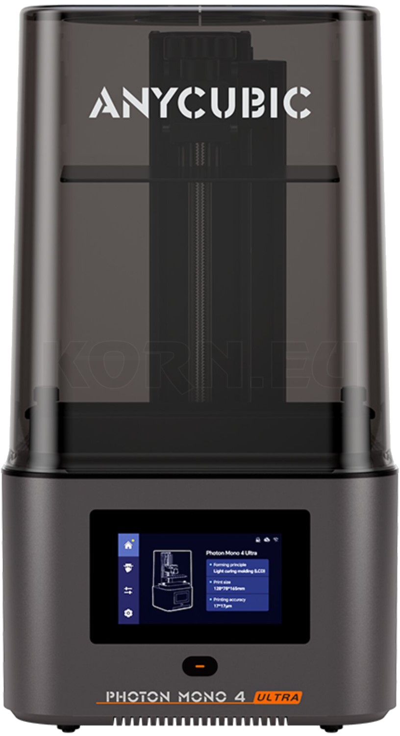
Anycubic Photon Mono 4 Ultra Resin 3D Printer for small model-making projects
Custom details in 1:160 and 1:220

3D Printing for N and Z – Print Tiny Parts Reliably

Small crates, detailed façades and custom loads enrich even the tiniest layouts. Printable outlines, strong transitions and finishing that preserves detail are essential. When planning N and Z parts, work backwards from the finished, painted model.

From a robust body to fine detail

Which tiny parts make good first projects?

3D printing for N and Z: printing tiny parts is easier with compact shapes than with long, freestanding rods. Start with an object that you can hold, clean and paint. For a goods shed, FDM walls, resin-printed crates and ready-made railings can work well together.

Choosing projects for N and Z: possibilities and clear limits
Project N scale – 1:160 Z scale – 1:220
Crates, barrels and compact loads A good starting point; resin for small joints and outlines. Also suitable; simplify details and plan safe points to hold the part.
Building shells and terrain forms FDM is useful if the surface finish suits the design. FDM for basic shapes; make small, visible decorative parts separately.
Windows, vents and façade reliefs Resin preferred; test openings and struts on a sample. Demanding; relief detail can replace open grilles.
Figures and groups of seated figures Resin with compact poses and reinforced transitions. Challenging; pose and silhouette matter more than tiny individual features.
Ladders, handrails and railings A difficult first project; consider wire and etched parts too. Often better made using mixed materials or ready-made accessories.
Gears, axle bearings and coupling mechanisms Functional testing required; this is more than a decorative task. Particularly demanding; beginners should use proven functional components.

The table offers guidance on construction methods. A resin printer does not guarantee an unbreakable ladder, and an FDM printer can certainly be useful for a small layout. The smallest feature you need is what matters, rather than the overall layout size alone.

Check the scale first

What actually shrinks between N and Z?

Under NEM 010, N uses a scale of 1:160 and a standard-gauge track width of nine millimetres; Z uses 1:220 and 6.5 millimetres. One full-size metre therefore becomes 6.25 millimetres or approximately 4.55 millimetres respectively. A person 1.80 metres tall measures 11.25 millimetres in N and about 8.18 millimetres in Z.

To convert an accurately scaled N file to Z, reduce its linear dimensions to 160 ÷ 220 × 100 = approximately 72.73 per cent. In the other direction, the factor is 137.5 per cent. An H0 file at 1:87 requires 54.375 per cent for N and approximately 39.55 per cent for Z. Check the source unit and actual dimensions after every import.

The conversion initially concerns external dimensions. Wall thicknesses, holes, handles and fits then need separate checks. Reassess any supports already prepared after changing size: their contact points will also become smaller and may no longer provide enough support.

Combine recognisable details with strength

Deliberately strengthen fragile details

Preserve the silhouette, adjust the cross-section

A full-size handrail 30 millimetres thick would have a diameter of just 0.1875 millimetres in N and approximately 0.136 millimetres in Z. These figures explain why exact scaling does not automatically produce a practical model. A slightly thicker handle or a separate wire part may work more convincingly on the layout.

Preserve the position, length and characteristic shape of important details. Reinforce vulnerable transitions on a hidden side wherever possible. On figures, arms held against the body, joined feet or an unobtrusive base can make handling easier. Assess the result from normal viewing distance too.

Use relief instead of a fully freestanding structure

A ventilation grille does not always need individual open louvres. A shallow relief on a solid background can preserve the effect and is easier to clean. Separate frames and clear film help with windows; in Z, a simpler arrangement of mullions may work better than numerous almost-closed gaps.

Plan material thickness and clear openings together. Every thicker strut takes up space. Place several variants side by side and decide only after cleaning, post-curing and a thin coat of primer. This tests the eventual model, rather than just the enlarged CAD view.

The thinnest wall is not a measure of quality

Manufacturers' minimum feature specifications apply to particular materials, printers and test conditions. A thin printed wall can still break during support removal. Surface area, unsupported length and subsequent loads also matter. For small resin housings, approximately 0.8 to 1.2 millimetres can be a robust design starting point; this range is neither a minimum wall thickness nor a specification for railing bars.

Print a sample before a batch

Match resolution and print profile sensibly

The following ranges are our suggested starting points for test prints, not tested N- or Z-scale profiles. Start with a manufacturer-recommended profile for the printer, material and nozzle. Change one parameter at a time and record the results.

Starting ranges and key checks in the slicer
Process Suggested test-print settings Key check
Resin for fine details A suitable 0.05 mm profile; compare 0.03 mm if needed. Correct exposure, clear gaps and supported islands.
FDM for larger main structures 0.4 mm nozzle with approximately 0.12–0.16 mm layer height. Continuous walls, visible stepping and suitable part division.
FDM for small, robust shapes Compatible 0.2 or 0.25 mm nozzle with approximately 0.08–0.12 mm layers. Actual toolpaths, cooling and sufficient layer time.

Pixel count is no substitute for calibration

Layer height describes stepping in the Z direction. Other properties matter for features in the printing plane; the display specification alone does not guarantee a particular level of part accuracy. With resin, unsuitable exposure settings can close gaps or weaken details. Do not copy a general exposure time in seconds from a different printer.

Compare raised lines, recesses and openings on a small test piece. If all holes are too tight, check the profile first. If only one extremely fine feature is missing, a design adjustment may be needed. Antialiasing can make edges look smoother, but it replaces neither printable geometry nor adequate strength.

Small FDM layers need time to cool

Very small individual parts take little time to print each layer. The next extrusion path may meet material that is still too soft. Check minimum layer time, minimum print speed and cooling appropriate to the material together. Several spaced-apart parts in each layer can allow time to cool; the print sequence must suit this approach.

A smaller nozzle allows finer line widths but requires a suitable profile and filament. Check the layer preview: thin features may be omitted or widened by the slicer. A lower layer height alone will not restore missing outlines in the printing plane.

Manageable and easy to compare

Cargo crates for N and Z as a first resin project

This planning example starts with a closed crate measuring 1,200 × 800 × 800 millimetres at full size. In N, this becomes 7.5 × 5 × 5 millimetres; in Z, approximately 5.45 × 3.64 × 3.64 millimetres. These dimensions are our own design example, not a report of a completed print test.

You need CAD software and a slicer, a compatible resin printer, suitable resin, the specified protective equipment, and supplies for cleaning and post-curing. Fine tweezers, a suitable cutting tool, a light-coloured catch tray and a painting holder are helpful for finishing.

1

Create the body and joints

Design the small crate as a solid part initially. With this compact geometry, you avoid a hard-to-reach cavity containing trapped resin. Suggest planks and fittings sparingly. A single clean outline often looks better than many grooves that disappear.

2

Compare two detail variants

For each scale, create one version with subtle joints and one with more pronounced joints. Keep the orientation and print profile the same. Clearly label the corresponding files so you can reliably identify each result later.

The finished surface decides

Clean and post-cure both samples according to the material instructions. Apply a thin coat of primer to one sample of each variant and compare the remaining outlines.

Approve a version for further copies

Make more copies only of the variant whose joints remain visible and whose edges survive handling.

3

Place supports on hidden surfaces

Choose an orientation with easily accessible contact points, preferably on the underside and the back that will later be hidden. Check every newly appearing island. A general angle recommendation is no substitute for checking the layers. Leave enough space for cleaning and tool access.

4

Assemble a small group of loads

Carefully finish the contact points and mount the crates on a separate load base. Dry-fit the arrangement first. A removable group is easier to paint and place in a goods wagon than many tiny parts glued in individually.

For ideas for the surroundings, see the guides to scratch-building buildings and platform design. With different proportions, the same exercise can become a toolbox or a compact distribution box.

Minimise support marks and paint thickness

Clean parts and remove supports carefully

Tiny parts must not get lost in the cleaning basket. Check its mesh size and, if needed, use a suitable holder approved by the equipment manufacturer. Follow the specific material instructions for cleaning, drying, post-curing and when to remove supports.

Cut accessible supports carefully while holding the part securely. A long remaining support stem can act as a lever and break away a thin corner. Move troublesome contact points for the next print. Heavy sanding of fine N- or Z-scale details can quickly remove more material than intended.

Use primer as a final detail check

Apply a thin coat of primer compatible with the material and allow it to dry as instructed. Thick filler coats can hide small joints. A temporary holder attached to a hidden surface makes painting easier and avoids frequent handling of the model itself.

Check that gaps remain open after each coat of paint. Keep push-fit and gluing surfaces clear where needed, and use glue sparingly. On a Z-scale façade, even one filled joint can change the appearance. Include finishing and painting when developing the test piece.

Follow the safety data sheet and manufacturer's instructions, particularly regarding suitable gloves, eye protection and ventilation. Water-washable resin also requires proper disposal: wash water containing resin must not go down the drain. Find suitable equipment in 3D accessories.

Spot faults before printing a whole batch

  • Details are already missing in the preview: correct units, scaling and geometry. Reprinting unchanged will not help here.
  • Openings are closed after printing: check dimensions and the material profile; calibrate exposure for resin.
  • Edges break during support removal: improve contact points, tool access and transitions. Change the material or construction method if needed.
  • Joints disappear only during painting: reduce paint thickness and repeat the detail sample, including primer.

Record the file, profile, material and successful finishing process together. Print another reference piece before larger batches. Tiny parts use little material, but hands-on work often dominates the time required. The 3D printing cost calculator helps you include failed prints and finishing too.

Choose material to suit use and handling

With resin, sharp outlines and toughness are different properties. A resin for decorative models may not also suit flexible snap-fit lugs. Check the material data and specified post-curing. Mix different resins only if the manufacturer provides a suitable procedure.

PLA is a natural starting point for many decorative FDM main structures used indoors. PLA+ refers to manufacturer-specific formulations. PETG may be useful for brackets under load; fine gaps and fits still need checking. The material name does not replace assessment of the specific part.

Pay attention to print-file quality too. Visibly angular curves can result from a coarse export. Check the mesh before slicing and, if needed, export it again at an appropriate resolution. Save the editable design together with the print file. This lets you change individual details later without rebuilding the entire model.

Explore the manufacturers' ranges

Compare printers, materials and accessories within each system.

Equipment for your N and Z projects

Find printers, filaments and resins

Search by product, material, colour or item number. Combine process, category and manufacturer filters. The list loads current products from the linked categories. Check printer compatibility and material properties on the product page.

The product list is being prepared. You can open the categories directly.

View all 3D tools

Frequently asked questions about printed N- and Z-scale models

Do I always need resin for Z scale?

Resin is often the more suitable approach for the finest visible details. Basic terrain shapes, building cores and auxiliary parts can also be made with FDM. Decide according to the part.

Can I directly reduce an N-scale file for Z?

72.73 per cent is suitable for the linear external dimensions of a file at 1:160. Wall thicknesses, openings, supports and fits then need separate checks.

Which layer height makes tiny parts reliable?

No layer height guarantees this on its own. Suitable 0.05 mm resin profiles, and 0.03 mm where appropriate, provide comparison points. Design, exposure and supports remain crucial.

Why do cleanly printed railings break?

A reproduced detail is not necessarily a load-bearing detail. Check cross-section, unsupported length, material and installation forces. Printed posts combined with wire can be an alternative.

Can I print small figures together?

Yes, after a successful sample. Every figure needs suitable orientation and supports. Allow room for cleaning and support removal; a full build plate is no proof of quality.

When is a printing service worthwhile?

It can make sense for a few specialist parts or if you lack a suitable workspace. Agree detail limits, material, support surfaces and finishing in advance. Read more: print your own models or use a printing service.

Technical background: MOROP NEM 010, Prusa on cooling and layer time, Anycubic on resin parameters and Formlabs on orientation and priming and painting. The project dimensions and starting ranges are our own planning examples.

Create your own scene from small details

Combine your printing projects with the topic guides for N scale and Z scale and build on a successful sample.

Explore the model railway guide