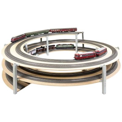
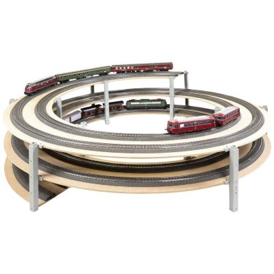
Coordinate radius, gradient and clearance
The key formulae
For a circular helix:
Track length in plan view = 2 × π × radius.
The gradient as a percentage is
100 × rise ÷ length in plan view.
For an oval, add both straight sections. Use the same unit throughout; a 3% gradient means a rise of 30 mm over 1,000 mm of horizontal track length.
To find the circular radius for a desired gradient, rearrange the formula:
Radius = 100 × rise ÷ (2 × π × gradient in percent).
A rise of 90 mm per turn at 2.5% gives approximately 573 mm. This describes the geometry only and does not replace testing with your rolling stock.
Worked examples for circular helices — not minimum dimensions
| Example |
Track centreline radius |
Rise per turn |
Gradient |
| H0, tight circle |
360 mm |
90 mm |
3.98% |
| H0, medium circle |
450 mm |
90 mm |
3.18% |
| H0, larger circle |
600 mm |
90 mm |
2.39% |
| TT, illustrative example |
450 mm |
70 mm |
2.48% |
| N, illustrative example |
300 mm |
55 mm |
2.92% |
Why a smaller helix is more demanding
For the same rise per turn, a smaller radius shortens the route and therefore increases the gradient. The curve also places additional demands on tractive effort. MOROP recommendation
NEM 101
gives recommended upper limits of 2.5% for standard-gauge main lines and 3% for branch lines. These limits should not be fully used on tight curves. Test running remains essential.
With two tracks, the outer track is longer and less steep for the same rise per turn. Where possible, use it for uphill running. Track spacing must suit the radius and vehicle overhang; a normal spacing on straight track does not automatically provide enough clearance on a curve.
When an oval shape makes sense
If more length is available along the edge of the layout, two straight sections between the semicircles can help. A radius of 450 mm and two straight sections of 300 mm each give approximately 3,427 mm of length in plan view per turn. With a rise of 90 mm, the gradient falls from around 3.18% for the circle to 2.63%. The footprint grows by 300 mm along the straight sections. Additional supports must not obstruct access to the centre.
Adding more turns alone does not reduce the gradient if the radius and rise per turn stay the same. Spreading the same total climb over more turns does reduce the gradient, but it also reduces the spacing between levels. Recheck vertical clearance and the exit position after every change to the plan.
Vertical clearance starts at railhead level
With a consistent construction, the approximate relationship is:
Vertical clearance = rise per turn − board thickness − height to railhead above the board − underside fittings.
With a 6 mm board and a 10 mm track assembly, 90 mm becomes just 74 mm. Joint plates, screws or tunnel overhead wiring can reduce this space further.
Check the complete vehicle envelope and allow extra clearance for construction tolerances. A hand needs more room than a vehicle. Plan access from the side or the centre accordingly. If pantographs are raised, separately allow for contact wire position, supports and the lead-in arrangement.