Modellbahn Keks
Welcome!
Our cookies offer you a fast, relaxed and full-featured shopping experience. Some are necessary to operate the website and its functions. Others help us to improve our services. If you agree to this, simply consent to the use of cookies for preferences, statistics and marketing by clicking on "OK". Alternatively, you can deactivate individual cookies under "Customise cookies" or all cookies, except those required for the function of our website, under "Reject all".
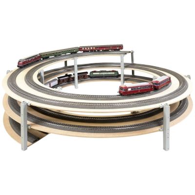
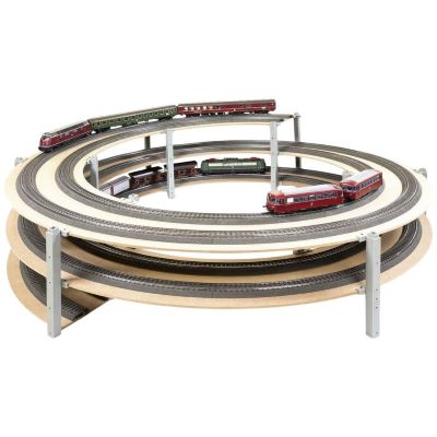
NOCH product image of a multi-level model railway helix
Layout Building · Gaining Height

Planning and Building a Model Railway Helix

A helix connects layout levels via a spiral track. The key requirements are a sufficiently large radius, a gradient your trains can handle and adequate vertical clearance. Use the calculator, construction guide and checklist to plan your connection to a hidden staging yard or the next scenic level.

Five decisions before the first cut

When planning and building a helix, start with your most demanding train: the longest coaches, the least powerful locomotive you intend to use and the heaviest formation. An individual vehicle may negotiate a radius that the complete train cannot manage on an uphill curve.

Decide on the entrance, exit and direction of travel. Then check the available space, including supports and a maintenance opening. A larger circle or an oval helix needs more floor space but allows a gentler gradient for the same rise per turn.

Helix calculator: plan with measurements

Enter all dimensions in millimetres. Measure the radius to the track centreline. The rise per turn is the height gained over one complete revolution, measured from railhead to railhead. For a circular helix, leave the straight length at zero; for an oval, enter the length of one of the two equal straight sections.

The preset values are a worked example, not confirmation of suitability for rolling stock, track spacing or overhead wiring.

The example values give an inner-track gradient of approximately 2.39% and 74 mm of vertical clearance. Enable JavaScript to calculate your own values.

The calculator determines the helix geometry only. Vertical transitions, approaches, supports, vehicle overhang and actual tractive effort require additional planning. Fractions of a turn change the direction of the exit.

Coordinate radius, gradient and clearance

The key formulae

For a circular helix: Track length in plan view = 2 × π × radius. The gradient as a percentage is 100 × rise ÷ length in plan view. For an oval, add both straight sections. Use the same unit throughout; a 3% gradient means a rise of 30 mm over 1,000 mm of horizontal track length.

To find the circular radius for a desired gradient, rearrange the formula: Radius = 100 × rise ÷ (2 × π × gradient in percent). A rise of 90 mm per turn at 2.5% gives approximately 573 mm. This describes the geometry only and does not replace testing with your rolling stock.

Worked examples for circular helices — not minimum dimensions
Example Track centreline radius Rise per turn Gradient
H0, tight circle 360 mm 90 mm 3.98%
H0, medium circle 450 mm 90 mm 3.18%
H0, larger circle 600 mm 90 mm 2.39%
TT, illustrative example 450 mm 70 mm 2.48%
N, illustrative example 300 mm 55 mm 2.92%

Why a smaller helix is more demanding

For the same rise per turn, a smaller radius shortens the route and therefore increases the gradient. The curve also places additional demands on tractive effort. MOROP recommendation NEM 101 gives recommended upper limits of 2.5% for standard-gauge main lines and 3% for branch lines. These limits should not be fully used on tight curves. Test running remains essential.

With two tracks, the outer track is longer and less steep for the same rise per turn. Where possible, use it for uphill running. Track spacing must suit the radius and vehicle overhang; a normal spacing on straight track does not automatically provide enough clearance on a curve.

When an oval shape makes sense

If more length is available along the edge of the layout, two straight sections between the semicircles can help. A radius of 450 mm and two straight sections of 300 mm each give approximately 3,427 mm of length in plan view per turn. With a rise of 90 mm, the gradient falls from around 3.18% for the circle to 2.63%. The footprint grows by 300 mm along the straight sections. Additional supports must not obstruct access to the centre.

Adding more turns alone does not reduce the gradient if the radius and rise per turn stay the same. Spreading the same total climb over more turns does reduce the gradient, but it also reduces the spacing between levels. Recheck vertical clearance and the exit position after every change to the plan.

Vertical clearance starts at railhead level

With a consistent construction, the approximate relationship is: Vertical clearance = rise per turn − board thickness − height to railhead above the board − underside fittings. With a 6 mm board and a 10 mm track assembly, 90 mm becomes just 74 mm. Joint plates, screws or tunnel overhead wiring can reduce this space further.

Check the complete vehicle envelope and allow extra clearance for construction tolerances. A hand needs more room than a vehicle. Plan access from the side or the centre accordingly. If pantographs are raised, separately allow for contact wire position, supports and the lead-in arrangement.

Choose suitable dimensions, from Z gauge to garden railways

The calculation principle applies to every scale. The required clearances depend on your rolling stock and track system. Radius designations such as R1 and R2 are manufacturer-specific; always compare dimensions in millimetres. For an overview, see the Track Atlas covering the different track systems.

Planning priorities by scale and gauge
Scale / gauge Pay particular attention to Further reading
Z and N Low vehicle weight, smooth track joints and access for cleaning. Z gauge track · N Unitrack
TT Long passenger coaches, spacing between parallel tracks and tractive effort on the inner track. Tillig TT · Roco TT
H0 Vehicle overhang, large steam locomotives, centre pickup shoes and the height of track with integral ballast. Märklin C Track · Roco Line
H0e, H0m, H0f, TTe and other narrow gauges Base the design on scale and vehicle envelope, not just the narrow track gauge. H0e track
S, 0, 1, II and G Larger diameters, heavier loads, stable supports and sufficiently wide access openings. 1 gauge · Garden railway track

Although an H0e locomotive runs on 9 mm track, it does not need the same clearance envelope as an N scale vehicle. Actual model dimensions are also decisive for unusual designs and very small scales such as T. MOROP documents NEM 102, NEM 103 and NEM 112 provide guidance on clearances and track spacing; NEM 104 is also relevant to narrow gauge.

Seven steps to an operational helix

To build your own, you need dimensionally stable trackbed segments, suitable supports or threaded rods, matching nuts and large washers, track, sound insulation and wiring materials. You will also need a saw, drill, measuring tools, abrasives and a secure work surface. Material thickness and support spacing must be matched; a generic board thickness does not guarantee adequate rigidity.

1. Draw the full-size plan

Mark track centrelines, board edges, supports and access points. With two tracks, the outer radius determines the footprint. Allow for lateral vehicle overhang, edge clearance and fixings beyond the track radius. Mark the entrance and exit, including their directions. Check the outline at the actual installation site.

2. Prepare trackbed boards and joints

Circular sections or trapezoidal segments can be cut to minimise waste. Smooth cut edges and make joints level and sufficiently rigid. Plates fitted underneath must be included in the clearance calculation. Stagger joints in laminated trackbed boards; check glued joints and any warping before assembly.

3. Align the base structure and height settings

Set up the base frame without twist. Threaded rods allow fine adjustment but need sufficiently wide bearing surfaces. With a rise of 90 mm and six equally spaced support positions, a circular helix of constant gradient rises by 15 mm between each position. Secure the nuts against movement afterwards without crushing the timber.

Mark measuring points consistently

A reference for every level
Distinguish railhead level from the board surface

Record the reference point for every dimension. Use the same measuring datum at all support positions so that construction heights do not add up unnoticed.

4. Ease the gradient at the entrance and exit

The transition from level to sloping track must not form an abrupt kink. Otherwise, long vehicles may ground, couplings may catch or wheels may lose load. Allow for transition lengths in addition to the constant-gradient part of the helix, and check the first track overlap particularly carefully. NEM 101 provides guidance on vertical transitions.

5. Fit insulation and track

Track underlay must be supported evenly. Avoid rigid adhesive bridges if the sound insulation is to remain effective. Flexible track allows freely chosen radii but requires carefully aligned ends. Check every joint for sideways misalignment and vertical steps. Sectional track must fit without mechanical stress.

6. Add wiring and protection against falls

Install power feeds before adding the next level. Route and label wiring outside the vehicle clearance space. Edge barriers keep derailed vehicles on the trackbed; their position must allow for vehicle overhang. Supports, nuts and cables must not touch rolling stock, including when trains pass each other.

7. Test every level thoroughly

Test slow uphill running, controlled downhill running and restarting with the heaviest or longest train you intend to operate. Check both directions and propelled formations where these will be used. On double-track helices, test your longest coaches passing each other. Add further levels and cladding only after successful testing.

A worked H0 project with three turns

For a height difference of 270 mm, our calculation uses three turns, each rising 90 mm, with a radius of 600 mm. This gives a gradient of approximately 2.39% and around 11.31 m of track within the helix. Approaches, vertical transitions and cutting waste are additional. The track centreline diameter is already 1,200 mm; the finished structure will be larger because of board edges and supports.

If using a kit, check its actual radii, level spacing and expansion options instead. Base sections and extension sections are not interchangeable. Even within one manufacturer's range, different generations of helix may use different components. Follow the instructions for the specific system when assembling and combining parts.

Power supply, maintenance and troubleshooting

Plan several suitable power feed points and a wire cross-section appropriate to cable length and operating current. Relying solely on rail joiners for electrical continuity makes later fault-finding more difficult. Define feedback sections and insulated gaps before laying track. A helix is not automatically an electrical reversing loop; what matters is how its track ends connect within the complete track plan.

Removable cladding, internal lighting and labelled connections make maintenance easier. Cameras help you monitor operation but do not replace access for recovery. Keep the rails clean and plan suitable track cleaning from the outset.

Keep a simple construction plan showing height marks, power feeds and removable joints. Also check whether a long coach can actually be taken out after a derailment. A large opening in the wrong place is of little use if supports or the next level block the recovery route. Avoid inaccessible turnouts within the helix as well.

The locomotive slips or stalls

First check rails, wheels, traction tyres and whether the rolling stock runs freely. Then reduce the train weight and test the same section again. If tractive effort is still insufficient, a larger radius, extra straight sections in an oval or a gentler gradient can help, provided adequate vertical clearance is maintained.

Vehicles derail in the same place

Check track joints, alignment, twisted trackbed boards and changes of gradient. Then inspect couplings and wheelsets. If the train only derails inwards under tension on a tight curve, also investigate the radius, the running resistance of the vehicles and the train formation.

Long vehicles catch or couplings come apart

Check overhang, parallel track spacing and local obstructions. If vehicles uncouple by themselves, pay particular attention to crests, dips and vertical steps in the track. Reproduce the fault slowly with the affected vehicle before adding extra equipment.

Find helices, track and building materials

Choose a product category and, if needed, a gauge. The product list loads from the shop; more results can be added page by page. The text filter searches the products already loaded. Always check the system, radius and dimensions before selecting an item.

Loading the product list. Alternatively, open the selected category directly in the shop.

Open the selected category in the shop

Explore suitable product ranges

Brands for your helix project

The track system and helix kit must be compatible in terms of their actual geometry.

Frequently asked questions about helices

What radius is right for an H0 helix?

The radius must suit your rolling stock, rise per turn and intended train load. A radius of 360 mm with a rise of 90 mm already gives approximately 3.98%. A larger radius provides a longer route and reduces the geometric gradient. Manufacturers' minimum radii must also be observed.

How many turns do I need?

Divide the total height to climb by the rise per turn. A height of 270 mm divided by 90 mm gives three turns. Allow for vertical transitions separately. Simply rounding up changes the final height if the rise per turn remains unchanged.

Can I build an oval helix?

Yes. Two straight sections make each turn longer. This reduces the gradient for the same rise. Allow for the larger footprint and support the straight sections adequately. Transitions between straight and curved track must be smooth.

Is a single-track helix enough?

It may be enough for alternating directions of travel if train movements are controlled appropriately. Two tracks provide separate routes but need more width. Automated operation requires planning for occupancy detection, routes and protection against opposing movements.

Do I need overhead wiring in the helix?

Only if your operating concept requires it. Running with raised pantographs needs suitable, continuous guidance. Lowered pantographs need less space. Your chosen operating method must also work reliably on the adjoining tracks.

Why does a long train fail despite a suitable radius?

Gradient, curve resistance, rolling resistance and train weight act together. Lighting pickups and couplings may add resistance too. Test the complete train, including restarting at the most demanding point, before finally enclosing the layout.

Continue planning your complete layout

Integrate your helix with a carefully designed track plan, good access and a suitable operating concept. Find more fundamentals in the model railway guide.

Back to the main guide