Clean Wheels and Pickup Shoes
Interruptions in current collection can look exactly like poor motor control.


Does the locomotive jerk at speed step 1, jump when starting, fluctuate in speed or cause the motor to become unusually warm? That does not automatically mean the motor-control settings are wrong.
The Motor Control Workshop separates current-collection faults, mechanical problems, speed curves and load compensation. Only after the drive is technically sound should manufacturer-specific decoder parameters be adjusted in a controlled way.
A modern locomotive decoder does not simply supply the motor with a constant DC voltage. Instead, the motor voltage is switched on and off rapidly using pulse-width modulation, or PWM. During short measuring intervals, the decoder can evaluate the back electromotive force generated by the rotating motor.
This allows the electronics to determine whether the motor is turning faster or slower than requested. When the locomotive enters a gradient or pulls a heavier train, load compensation can increase motor output. On a downhill section, less power is required. Correctly configured motor control therefore helps the locomotive maintain a more consistent speed under changing load.
Good control is especially visible at very low speeds: shunting, coupling, entering a station or crawling through a complex turnout formation. The locomotive should run without visible surging, should not jump from speed step 0 to 1 and should not twitch immediately before stopping.
However, the factory settings of modern decoders already work well in many vehicles. Optimisation is useful only when there is a reproducible problem. Changing five motor-control parameters without a clear reason often creates more problems than it solves.
Select the observed behaviour, decoder family and motor type. The assistant deliberately recommends a diagnostic route rather than universal CV values because motors, gearboxes, firmware versions and decoder families respond differently.
Check current collection and the mechanism. Only then test the parameters for the low-speed range specified for the exact decoder family, using small adjustments.
Test: first without a train on straight track, then with the normal train load and on a gradient.
Interruptions in current collection can look exactly like poor motor control.
Gears, bearings, cardan shafts and worms must not bind, run dry or be damaged.
Worn brushes, dirty commutators or damaged motors cannot be repaired electronically.
Follow the manufacturer's instructions for capacitors and chokes. Unsuitable suppression circuits can interfere with motor-control measurements.
Continuous and peak motor current must remain within the decoder's permitted load.
A locomotive that simply runs too fast does not automatically need different load-control settings.
Use low momentum during diagnostic runs so that changes to motor-control parameters become visible immediately.
Save the relevant CV values or the complete decoder project before changing the first motor-control parameter.
Modern decoders work well with many conventional and five-pole DC motors using their factory settings. Fine-tuning is normally required only when there is a clearly visible problem.
Sensitive coreless motors can react strongly to PWM frequency and control parameters. Use only settings expressly permitted by the vehicle and decoder manufacturers.
Before optimising the decoder, check brushes, commutator, bearings, gearbox, suppression components and current collection. Mechanical friction can otherwise create misleading control behaviour.
Mechanical inertia acts in addition to electronic motor control. Close to standstill, braking delay, flywheel effect and low-speed control can influence one another.
Short current-pickup bases and small flywheels make contact problems particularly visible. Aggressive control settings must not be used to conceal this underlying fault.
Higher currents and large changes in load require adequately rated decoders and cooling. Always test settings with the normal train load as well.
This overview is intended only as an orientation. The current instructions and firmware version for the exact decoder family installed in the vehicle remain authoritative.
| Decoder Family | Typical Parameters | Recommended Starting Point |
|---|---|---|
| ESU LokPilot / LokSound 5 | Depending on the generation, parameters can include reference voltage, control gain, inertia and PWM. Current LokPilot 5 families commonly use motor-control parameters around CV51 to CV55. | Begin with the factory configuration, a suitable motor profile or the automatic motor-tuning procedure documented for the decoder. Change only one parameter afterwards. |
| PIKO SmartDecoder XP | Auto-adaptive motor control plus additional settings contained in the decoder project, firmware and product-specific documentation. | Check the factory configuration and SmartProgrammer project before making manual adjustments. |
| ZIMO MX / MN / MS | Depending on the decoder family, parameters can include PWM and measuring behaviour, control characteristics and reference voltage; examples include CV9, CV56 and CV57. | Identify the exact decoder family and current manual, then test small changes at low speed and under load. |
| Lenz Standard / Silver / Gold | Motor profiles are selected using CV50 on suitable decoder families, with additional fine-tuning parameters such as CV113 and CV114 where documented. | Select the appropriate motor profile first and only then fine-tune the parameters provided for that profile. |
| Uhlenbrock IntelliDrive | Depending on the decoder, motor-control parameters can be located in the area from CV53 to CV58. | Match the exact product number with the correct decoder manual because value ranges and functions differ between families. |
| Märklin mLD3 / mSD3 | Motor type, speed curve and control parameters are configured using the Märklin Decoder Tool, a compatible Central Station or suitable decoder programming. | Select the correct motor type or appropriate vehicle project and do not treat factory-fitted OEM decoders like universal retrofit decoders. |
Determine the manufacturer, family, firmware version and interface.
Save the original project or all relevant CV values.
Check current collection, motor, gearbox and lubrication.
Keep acceleration and braking delays low during diagnosis.
Correct minimum and maximum speed before fine-tuning motor control.
Run an automatic motor-calibration procedure only when it is explicitly described for the decoder and a clear test track is available.
Use small increments and document every adjustment.
Compare speed step 1, medium speed and repeated starts in both directions.
Test again with the normal train and on a gradient.
Only after motor control is stable should acceleration, braking and sound be permanently fine-tuned.
Record every test run. The log is stored exclusively in the local browser and makes it easy to compare the old value, new value and observed driving behaviour.
| Gauge | Typical Challenge | Particularly Important to Check |
|---|---|---|
| Z | very small motors and little flywheel effect | very small adjustments, temperature and perfect current collection |
| N | small motors and restricted body space | decoder dimensions, motor temperature and installation with the body fitted |
| TT / TTe | different generations of motors and gearboxes | mechanism and suppression components on older models |
| H0 | very wide variety of motors and decoder families | motor type, interface, current requirement and manufacturer parameters |
| H0e / H0m / H0f | short current-pickup base and little installation space | do not conceal contact problems with aggressive load compensation |
| 0 | larger motors and additional functions | motor current, flywheel, couplers and sound |
| 1 / G | high current, gradients and heavy trains | power reserve, cooling and behaviour with the normal train load |
The controller may be intervening too strongly. Check that the drive runs freely and then adjust only the relevant manufacturer-specific gain parameter carefully.
Check current collection, minimum speed and the parameters used for the low-speed range.
The starting voltage may be too high or the mechanism may require excessive force to start moving.
Braking delay, flywheel effect and special low-speed parameters can interact.
Check motor power, voltage drop, wiring, pickup shoe and mechanical friction before changing the control reference.
PWM frequency or the measuring method may not suit the motor. Restore the saved original value and consult the manufacturer instructions.
Switch off track power immediately. Check the mechanism, motor current, wiring and permitted PWM configuration before further testing.
This is first a current-collection problem. Check wheels, pickup shoes, wheel contacts and frog power supply.
First match the minimum, mid-range and maximum speed of both locomotives. Then compare load control and acceleration and braking delays.
When replacing a decoder, the motor current, interface, installation dimensions, digital protocol and required function outputs must suit the vehicle.
Variable PWM frequency, extensive load control and an automatic motor-tuning function for suitable applications.
View Product →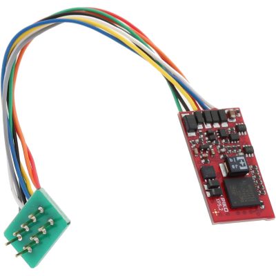
Multi-protocol decoder with auto-adaptive motor control and extensive braking functions for H0 vehicles.
View Product →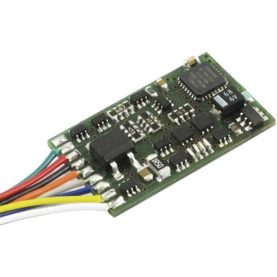
DCC locomotive decoder with high-frequency motor control and RailCom for conventional H0 conversions.
View Product →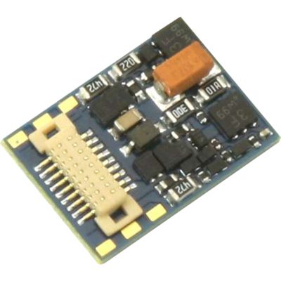
Compact multi-protocol decoder for small vehicles and particularly restricted installation space.
View Product →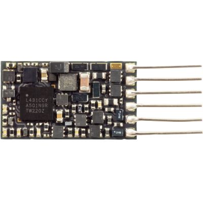
Particularly low-profile decoder for small vehicles with restricted installation space.
View Product →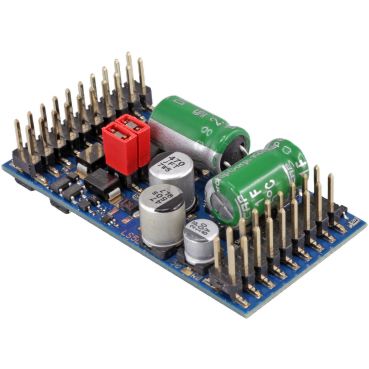
High-output locomotive decoder for larger motors and large-scale vehicles.
View Product →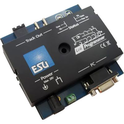
Save and configure driving, motor, function and sound parameters graphically.
View Product →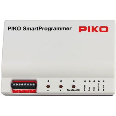
Configure compatible PIKO SmartDecoders, save projects and test vehicle functions.
View Product →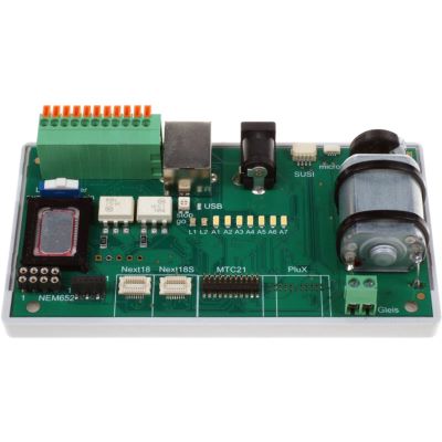
Read and program decoders outside the vehicle and test motor and function outputs using compatible interfaces.
View Product →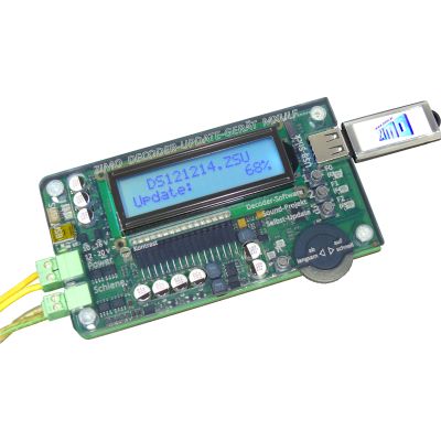
CV programming, firmware maintenance and sound transfer for compatible ZIMO decoders.
View Product →Product Radar searches current English decoder pages and manufacturer ranges. Every discovered product detail page is checked again before display. Products with an archive notice are excluded, small preview images are normalised to the 400-pixel shop version and delivery or stock information is deliberately not displayed on the product cards.
Live checking will begin when you approach this section.
Motor control attempts to maintain the requested motor speed despite changing loads. The speed curve determines which internal speed is assigned to a particular speed step.
There is no single manufacturer-independent motor-control CV. ESU, PIKO, ZIMO, Lenz, Uhlenbrock and Märklin use different parameter groups and procedures.
Common causes include dirty contacts, a binding mechanism, an excessive minimum speed or unsuitable control parameters for the low-speed range.
Properly configured load compensation is beneficial for many modern DC and coreless motors. For unusual or historic motor designs, check the decoder manufacturer's instructions first.
Yes. Unsuitable PWM settings, mechanical binding, excessive motor current or extreme control parameters can cause abnormal heating. Stop operation immediately if the motor or decoder becomes unusually hot.
The decoder performs a defined test run and determines suitable control parameters. The procedure is manufacturer-specific and requires a clear and sufficiently long test track.
Possible causes include insufficient motor power, voltage loss, poor current collection, mechanical friction or an unsuitable control reference. Not every fault can be corrected electronically.
Use only settings expressly approved by the vehicle and decoder manufacturers for that motor type. PWM frequency, motor current and heat generation are especially important.
The PWM frequency or measuring method may not suit the motor. Restore the saved original setting and check the instructions for the exact decoder family.
Many DCC decoders support Programming on Main. For extensive experiments, however, a dedicated programming and test track is clearer and safer.
First match the minimum, mid-range and maximum speeds. Then tune the motor control and acceleration and braking behaviour of both locomotives.
A reset can be useful when several unknown parameters have been changed and a working baseline can no longer be restored. Use only the reset command specified for the exact decoder family.
The comprehensive Model Railway Guide covers decoders, interfaces, digital command stations, driving dynamics, maintenance, track and layout planning.