Acceleration Delay
Controls the programmed acceleration rate. A higher value normally produces a more gradual increase in speed.

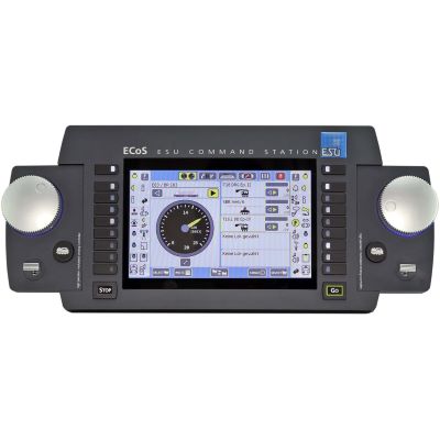
A heavy freight locomotive should not leap away like a railcar. A shunting locomotive, on the other hand, needs to respond quickly to the controller. CV3 and CV4 allow digital driving dynamics to be matched to the vehicle, train type and layout.
This workshop connects CV values with measurable times and stopping distances, explains shunting mode, switchable momentum, sound, braking sections and constant stopping distances, and shows why the same values can behave differently with different decoders.
A locomotive decoder receives a requested speed step from the digital command station. Without programmed momentum, it attempts to reach the new target relatively quickly. That may work technically, but the sudden change in speed often looks unnatural on a model railway.
The acceleration delay defines how quickly the decoder's internal target rises from a lower to a higher speed. In the standard DCC system this basic function is controlled by CV3. The braking or deceleration delay works in the opposite direction and is configured with CV4.
Both settings are independent. A shunting locomotive can use a short acceleration time and short braking time. A heavy freight locomotive can build up speed gradually and coast for much longer. With a sound decoder, engine revving, load changes, idle sounds and brake effects should also match the visible movement.
It is important to distinguish this from motor control . If a locomotive already jerks at speed step 1, a high CV3 value does not repair the technical cause. Reliable current collection, a free-running mechanism, suitable starting voltage and stable load control must come first.
These calculators deliberately provide reference values rather than guaranteed results. Under the standard DCC calculation, the acceleration or deceleration rate is based on 0.896 seconds multiplied by the CV value and divided by the number of speed steps in use. Across the complete speed-step range this corresponds approximately to CV value × 0.896 seconds. Manufacturers can nevertheless use different scaling, internal speed steps, soft-start ramps or additional braking functions, so the factor can be adjusted below.
Calculates an approximate full-range acceleration or braking time.
Approximate full-range DCC reference for CV value 15.
Whenever possible, use the actual factor and behaviour described in the manual for the exact decoder family.
Useful when a locomotive should take approximately a defined number of seconds to reach its configured maximum speed.
Fine-tune the result with a test run on the layout.
The value range and scaling defined by the decoder manufacturer remain authoritative.
Approximation for uniform deceleration from a specified prototype speed to a complete stop.
Physical approximation assuming uniform deceleration.
Decoder speed curves, actual model speed, flywheel, gradient, train load and rolling resistance can all alter the real stopping distance.
Controls the programmed acceleration rate. A higher value normally produces a more gradual increase in speed.
Controls the programmed deceleration rate. The value does not define a fixed stopping distance in centimetres.
Optional NMRA adjustment used to add to or subtract from the basic acceleration rate, for example when adapting momentum for different train loads or consists. Decoder support must be checked.
Optional adjustment corresponding to CV23 for the braking rate. Its practical implementation and support depend on the decoder.
On compatible decoders, set this sensibly before final braking tests because a higher speed increases the distance travelled during the same braking time.
Many decoders traditionally use a function button to disable acceleration and braking momentum. F4 is common, but the actual button may be changed through function mapping.
Compatible DCC decoders can detect an asymmetrical DCC track signal. The braking parameters used are manufacturer-specific.
Some modern decoders provide a dedicated stopping-distance function. This is not the same as the time-based delay controlled by CV4.
Universal CV values are rarely useful. Convincing driving behaviour should reflect the vehicle type, train mass, operating purpose and available track length.
Short acceleration and braking times. A switchable momentum override or easily accessible shunting mode is particularly useful for precise coupling movements.
Brisk but not abrupt acceleration. Choose braking behaviour that allows short platforms and frequent stops to be reached reliably.
Medium to longer acceleration. Set a realistic maximum speed first and then fine-tune CV4.
Gradual load take-up, long acceleration and controlled coasting make the mass of a heavy freight train much more convincing.
Tune visible acceleration and the sound sequence together. Exhaust beats, load changes and brake effects should match the movement.
Match the speed curves first. Then adjust acceleration and braking times so that both locomotives behave as similarly as possible.
Check the manufacturer, decoder family and instructions. Record the permitted value range, time factor and additional momentum functions.
Test with very little programmed momentum. The locomotive must already run smoothly and evenly without a long acceleration delay.
Excessive model speed distorts every stopping-distance measurement carried out afterwards.
Define a starting point, measuring point and stopping point. Always compare settings under the same conditions.
Increase the value gradually until the acceleration suits the vehicle class and normal train load.
Start braking from the same speed every time and measure the actual stopping point.
Check momentum override, shunting speed and function buttons during real coupling and yard movements.
Record the locomotive address, decoder, CV3, CV4, maximum speed, momentum button and any special settings.
CV4 fundamentally creates a time-based deceleration. If a reproducible stop in front of a signal or platform is required, the initial speed and braking system must also be controlled.
A faster train covers more distance during the same braking period. The same CV4 value therefore does not automatically produce the same stopping point.
Compatible DCC decoders can detect an asymmetrical track signal. Depending on the decoder, the normal CV4 delay or a separate braking-distance function may be used.
Some decoders provide a dedicated function for more reproducible stopping distances. Separate parameters and, in some cases, calibration procedures apply.
Multi-protocol decoders may support additional braking methods using DC voltage or special signal sections.
The decoder controls the motor, but flywheel effect, gearbox characteristics, wagon resistance and gradients influence the visible movement.
Automated layouts can use feedback detectors and software speed profiles. Decoder momentum then needs to be coordinated with the layout-control system.
CV3 and CV4 are widely supported. Additional momentum profiles, function-button assignments, constant stopping distances and programming tools can nevertheless differ considerably.
PIKO documents an additional soft-start and braking ramp controlled through CV53 on suitable SmartDecoder XP families. If changes to CV3 and CV4 appear to have little effect, check the exact decoder documentation and firmware first. Current XP firmware also provides a prioritisation setting allowing the decoder to prioritise either the soft-start ramp or the CV3/CV4 acceleration and braking delay. Never transfer these PIKO-specific settings to other decoder families.

DCC locomotive decoder with extensive motor-control settings and several supported braking methods.
View Product →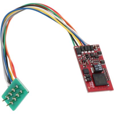
Modern multi-protocol decoder with extensive driving, braking and configurable momentum functions.
View Product →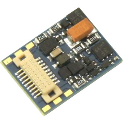
Compact multi-protocol decoder for small vehicles and restricted installation spaces.
View Product →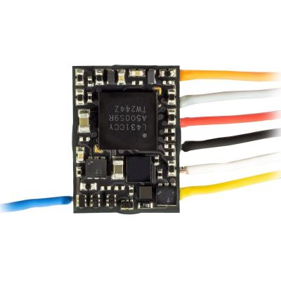
Very compact decoder for TT and N vehicles with limited installation space.
View Product →| Gauge World | Typical Challenge | Recommended Driving Test |
|---|---|---|
| Z Gauge | very short layout distances and sensitive current collection | use small value changes, clean track and sufficient safety distance |
| N Gauge | long trains on a compact layout | test the stopping distance using the longest train operated regularly |
| TT / TTe | shunting and main-line operation on the same layout | test momentum override and normal main-line settings separately |
| H0 / H0e / H0m / H0f | very different vehicles, decoders and train types | select values by vehicle class instead of using one setting for the whole fleet |
| Gauge 0 | strong visual vehicle mass and many additional functions | tune sound, digital couplers and braking sounds together |
| Gauge 1 | large vehicles and long visible coasting distances | use a long test section and sufficient safety margin before the end of the track |
| G Gauge | heavy trains, gradients and changing loads | test with both light and heavy trains and on gradients |
Check whether momentum has been disabled using a function button or whether an additional decoder function is taking priority over the normal CV3/CV4 ramp.
First reduce an unrealistically high maximum speed. Then reduce CV4 and test again from exactly the same initial speed.
A purely time-based delay does not guarantee an identical stopping point. Check a braking section or dedicated constant stopping-distance function.
Temporarily reduce CV3 and check current collection, gearbox, starting voltage and motor control.
Sound projects often require a particular speed, sufficiently strong deceleration or speed step 0 before the braking sound is triggered.
Match minimum and maximum speeds, speed curves, CV3 and CV4 of both locomotives as closely as possible.
Product Radar reads current English decoder categories and manufacturer pages. Discovered product detail pages are checked before display. Products with a detected archive notice are excluded, smaller preview images are normalised to the 400-pixel shop version and delivery or stock information is deliberately not displayed on this landing page.
Live checking will begin when you approach this section.
Acceleration and braking are only two parts of a convincing digital locomotive setup. A well-configured model also needs a suitable maximum speed, smooth motor control, sensible function assignments, an appropriate sound project where fitted and reliable current collection.
On DCC locomotive decoders, the standard acceleration delay is normally configured with CV3. Manufacturers may additionally provide separate soft-start ramps or alternative momentum profiles.
The standard DCC braking or deceleration delay is normally configured with CV4. Under the usual interpretation, a higher value produces a longer deceleration period.
Under the standard DCC definition, value 0 means that no programmed acceleration or braking momentum is applied. Additional decoder functions can nevertheless affect the behaviour.
There is no universal CV value. Decoder scaling, vehicle type, maximum speed, train load and available layout length all matter. Tune the locomotive by measured time and visible behaviour.
Under the standard DCC full-range reference calculation using 0.896 seconds per CV value, CV3 = 10 corresponds to approximately 8.96 seconds. Manufacturers can use different scaling or additional ramps.
CV4 fundamentally creates a deceleration period. A faster vehicle travels farther during the same amount of time.
Many decoders support a momentum override. F4 is commonly used by tradition, but the actual function button may be assigned differently through function mapping.
Shunting mode normally reduces the maximum speed or changes the usable speed-step range. Momentum override removes the programmed acceleration and braking delay. Both functions can be available independently or together.
A constant stopping distance is an additional decoder function and is not created solely by CV4. Required parameters and any calibration procedure are manufacturer-specific.
This depends on the decoder and its configuration. Some decoders use the normal braking delay while others use separate stopping-distance or braking parameters.
Check current collection, mechanism, starting voltage and motor-control parameters. CV3 is a momentum setting and cannot repair a technical fault.
First match minimum, mid-range and maximum speed. Then adjust CV3 and CV4, or the measured acceleration and braking times, so that both locomotives behave as similarly as possible.
The comprehensive Model Railway Guide covers decoders, digital command stations, motor control, sound, track, vehicles, maintenance and layout planning.