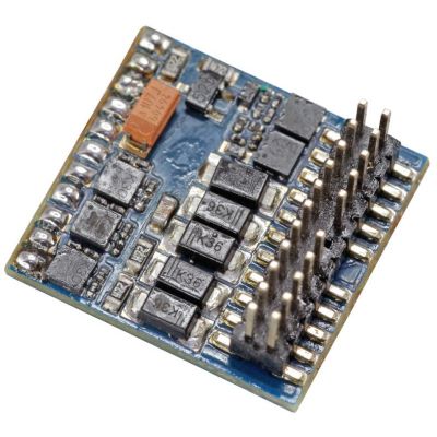




Vehicle Side
Two-Row Female Header
The locomotive circuit board has two parallel rows with eleven positions in each row.
Check
Position 11 must be blocked or manufactured without a hole.

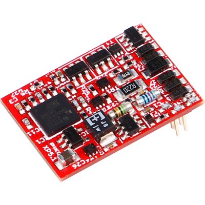
PluX22 connects the motor, track pickups, lighting, loudspeaker, energy storage and numerous auxiliary functions through a compact plug-in connection. This guide explains how to identify PluX22 and choose a suitable locomotive, function or sound decoder.
PluX22 belongs to the PluX family defined by NEM 658. The vehicle circuit board carries a two-row female header. The decoder has the matching pins on its underside and is plugged directly into the vehicle circuit board.
The name describes 22 mechanical positions. Position 11 is blocked as the index and has no electrical contact. This leaves 21 electrical connections. The keying prevents the decoder from being inserted after being rotated or shifted sideways.
PluX22 carries both track connections, both motor connections, front and rear lighting, up to seven additional amplified outputs, logic-level or train-bus connections, loudspeaker connections and power-supply contacts for energy storage.
The interface does not determine the digital protocol. A PluX22 decoder may support DCC, Motorola, Selectrix or mfx-compatible registration. The protocol, motor current, dimensions and range of functions must therefore be checked separately.
The locomotive circuit board has two parallel rows with eleven positions in each row.
Position 11 must be blocked or manufactured without a hole.
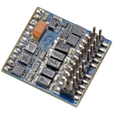
The pin header projects from the underside of the decoder board into the vehicle socket.
Do not confuse it with 21MTC.
Vehicles and decoders should be identified clearly as PluX22 on the packaging or in the instructions.
Compare the production series and article number.
Analogue vehicles often have a blanking plug that connects the motor and lighting.
Remove the blanking plug straight and with the power off.
Circuit-board components, body supports and wires may reduce the usable space.
Measure the length, width and height separately.
Not every vehicle uses all PluX22 contacts for lighting, couplings or special functions.
Consult the circuit diagram and function description.
Position 11 forms the mechanical key. The pin is omitted on the decoder side, while the corresponding vehicle socket position is blocked. This allows the decoder to be inserted only in the intended orientation.
PluX22 therefore has 22 numbered positions but only 21 electrical contacts. A decoder must never be forced into the interface. Resistance indicates incorrect alignment, bent pins or an unsuitable interface.
| Pin | Designation | Function | Output Type | Important Note |
|---|---|---|---|---|
| 1 | GPIO_C | Universal input or output | Logic level | Do not connect high-current loads directly |
| 2 | AUX3 | Third auxiliary function output | Amplified | Observe the decoder output-current rating |
| 3 / 4 | GPIO_A and GPIO_B | Train bus or additional logic functions | Logic level | The vehicle circuit board requires suitable amplifiers |
| 5 / 6 | GND and Cap+ | Decoder negative and energy-storage connection | Power supply | Connect the energy-storage circuit only according to the instructions |
| 7 / 13 | F0 Forward / Reverse | Front and rear headlights | Amplified | Check the direction-dependent assignment |
| 8 / 10 | Motor Positive / Negative | Decoder motor output stage | Regulated | Measure the motor current under load |
| 9 | U+ | Decoder positive after the rectifier | Power supply | Do not connect it to a separately generated vehicle positive |
| 11 | Index | Mechanical keying | No connection | The position remains blocked |
| 12 / 14 | Right / Left Track Pickup | Current pickup and digital signal | Track input | Do not confuse these with the motor connections |
| 15 / 17 | Loudspeaker A / B | Sound-decoder loudspeaker connection | Audio | Do not connect to the vehicle ground |
| 16 / 18 | AUX1 / AUX2 | First and second auxiliary functions | Amplified | Often used for tail lights or cab lighting |
| 19–22 | AUX4 to AUX7 | Four additional auxiliary functions | Amplified | Check how the locomotive circuit board actually uses them |
| Interface | Positions | Typical Installation Space | Strengths | Important Consideration |
|---|---|---|---|---|
| NEM 652 | 8 contacts | Depends on the wired decoder | Simple and widely used | Only a few functions in the basic connector |
| PluX12 | 12 positions | Up to 20 × 11 × 4.2 mm | Compact | Not preferred for new vehicle designs |
| PluX16 | 16 positions | Up to 20 × 11 × 4.2 mm | Sound and several functions | Fewer amplified outputs than PluX22 |
| PluX22 | 22, including one index position | 30 or 35 × 16 × 6 mm | Motor, sound, energy storage and many functions | Check the standard and vehicle space together |
| 21MTC | 22 positions with 21 contacts | Separate NEM dimensions | Feature-rich H0 models | Pins are located on the vehicle circuit board |
The decoder requires sufficient reserve for the motor under realistic load conditions.
The vehicle space and the dimensions of the specific decoder must be checked together.
Headlights, tail lights, cab lighting, couplings and smoke units require suitable outputs.
GPIO connections frequently require an amplifier circuit on the vehicle circuit board.
The impedance, sound enclosure, sound project and available space must all be compatible.
Energy-storage modules may only be connected according to the manufacturer's circuit diagram.
DCC, Motorola, Selectrix and mfx are decoder features, not properties of the PluX22 socket.
PluX22 is usually too large. Next18, E24, NEM 651 or wired decoders are more common.
Very large multiple units or specialist vehicles.
Some modern vehicles use PluX22, although PluX12, PluX16 and Next18 are more common.
Available decoder length and body height.
PluX22 is particularly widespread in modern diesel, electric and steam locomotives.
Numerous independently controlled lighting and sound functions.
Some compact Gauge 0 models may use PluX22. The motor current must be checked particularly carefully.
Continuous current, starting current and heat dissipation.
High-capacity decoders with wires, screw terminals or PluG are generally more suitable for large-scale railways.
Multiple motors and high auxiliary currents.
The socket fitted is only the first step. The output capacity, installation space and vehicle circuit board remain decisive.
Open the locomotive, photograph and measure it, and compare the instructions.
The motor, current pickup and lighting must operate reliably.
Release screws, clips and wires according to the instructions.
Photograph the index position, blanking plug and circuit-board markings.
Pull it straight out of the female header and retain it safely.
Align the pins and never press on components or the pins themselves.
Read the address and test the motor, lighting and functions individually.
The pin side and electrical assignment are completely different.
This can bend the pins or damage circuit-board tracks.
Different production series may have different circuit boards.
GPIO pins frequently require an amplifier circuit.
The loudspeaker and sound enclosure require additional room.
The polarity, voltage and charging circuit must suit the decoder.
The selection includes universal locomotive decoders, function decoders for control cars, blank sound decoders and model-specific sound solutions. The linked product cards do not contain an availability statement.
For precise motor control, driving lights, couplings and additional vehicle functions.
Modern motor control and extensive function mapping.
View Product →
DCC decoder with RailComPlus and ABC functions.
View Product →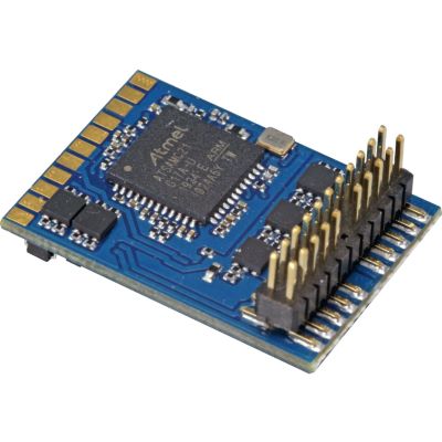
Versatile DCC version for modern H0 locomotives.
View Product →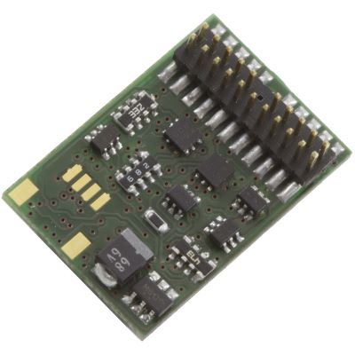
DCC decoder with ABC technology and RailCom.
View Product →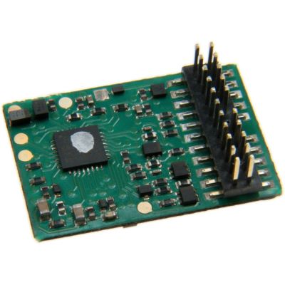
Locomotive decoder with multiple outputs and an energy-storage option.
View Product →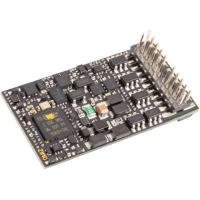
Single-sided decoder with numerous functions.
View Product →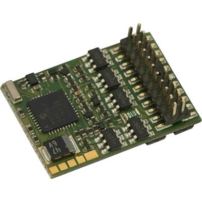
High-capacity decoder with numerous outputs.
View Product →PluX22 provides numerous independently controlled lighting and auxiliary functions without a regulated motor output.
Blank decoders and prepared sound projects for H0 vehicles and individual Gauge 0 models.
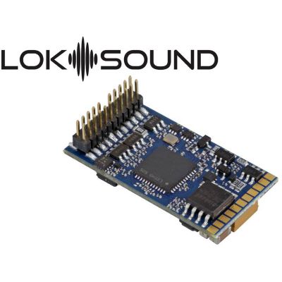
Universal sound decoder for custom projects.
View Product →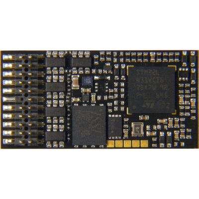
Sound decoder with extensive digital functions.
View Product →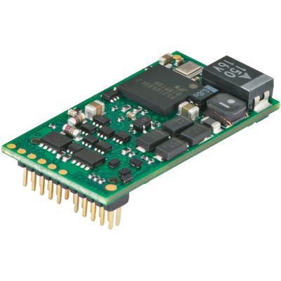
Sound decoder for mfx, DCC and Motorola operation.
View Product →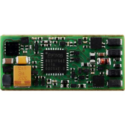
Universal basis for individually loaded sound projects.
View Product →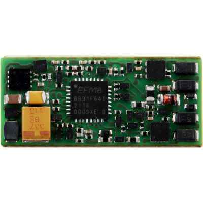
Sound decoder with a prepared sound project.
View Product →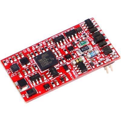
Free choice of sound project and multiprotocol operation.
View Product →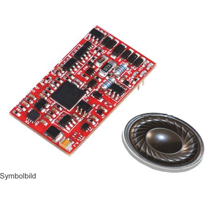
Model-specific sound solution with a loudspeaker.
View Product →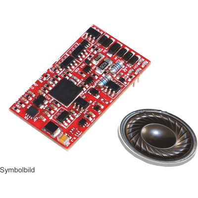
Electric-locomotive sound project for suitable Class 141 models.
View Product →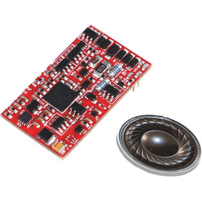
Sound project for the modern diesel shunting locomotive.
View Product →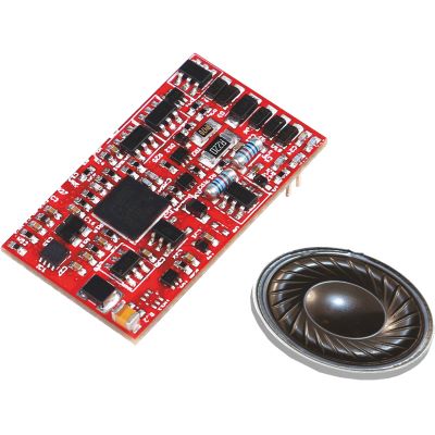
Diesel-locomotive sound for suitable Class 107 models.
View Product →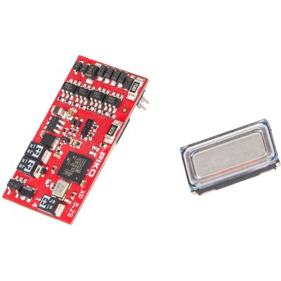
Steam-locomotive sound project with a suitable loudspeaker.
View Product →PluX22 has 22 numbered positions. Position 11 is blocked as the mechanical index, leaving 21 electrical contacts.
NEM 658 provides for dimensions of up to 35 × 16 × 6 mm. RCN-122 uses a maximum of 30 × 16 × 6 mm for harmonisation with 21MTC.
This may be mechanically possible. The additional outputs and functions of the PluX22 interface will then remain unused.
Only when the vehicle circuit board, unused holes and installation space expressly permit it. It must never be inserted with force.
Yes. The interface provides two loudspeaker connections and numerous contacts for sound, lighting and auxiliary functions.
PluX22 provides GND, U+ and Cap+. The specific circuit must, however, comply with the decoder instructions.
With PluX22, the pins are located on the decoder. With 21MTC, the vehicle circuit board normally carries the pins.
F0 forward, F0 reverse and AUX1 to AUX7 are generally intended as amplified outputs. GPIO connections provide logic levels.
No. The interface is independent of the protocol. Decoders may support DCC, Motorola, Selectrix or mfx.
PluX22 is particularly widespread in modern H0 locomotives. Individual TT, H0e and Gauge 0 vehicles may also be equipped with it.
Possible causes include missing function mapping, an unassigned vehicle circuit board connection, a logic-level output or a different circuit-board assignment.
Professional installation is advisable when pins are bent, the circuit-board assignment is unknown, the motor current is high, the vehicle is valuable or a complex sound conversion is planned.
The contact assignment, index position, dimensions and installation guidance of NEM 658, 2025 edition were considered.
Content status: 17 July 2026. Check the current vehicle and decoder instructions before installation.
The main guide covers locomotive decoders, sound decoders, digital command stations, protocols, digitisation and layout planning.