
SUSI: Expansion Interface for Sound and Auxiliary Functions
What does SUSI mean, how do classicSUSI, microSUSI and powerSUSI differ and when can a sound module be retrofitted? This guide explains the connection, data transmission, SUSI-BiDi, CV ranges, gauges, installation and suitable digital products.
Module Bus
Serial User Standard Interface
What Is the SUSI Interface?
SUSI is an internal expansion interface for digitally controlled model railway vehicles. The name stands for Serial User Standard Interface. A main module, now normally referred to as the host, transmits driving and function information to one or more expansion modules.
The host may be a locomotive decoder, sound decoder or suitably equipped vehicle circuit board. Typical expansions include sound modules, additional function outputs, smoke and effect modules or other electronic assemblies. An existing locomotive decoder does not therefore necessarily have to be replaced completely when only sound or an additional function is required.
SUSI is neither a track protocol nor a normal vehicle decoder interface . DCC, Motorola and mfx-compatible formats are transmitted from the digital command station to the locomotive decoder through the track. Only inside the vehicle does the decoder pass suitable information to the expansion modules through the SUSI bus.
The interface must therefore be considered independently of whether the locomotive uses a decoder with Next18, NEM 651, NEM 652, PluX or 21MTC. On modern interfaces, certain contacts may alternatively be used as a SUSI connection. The decoder and locomotive instructions state whether this option is actually available in a particular vehicle.




Data, clock and power supply
How Does the SUSI Bus Work?
The classic interface combines serial data transmission with a power supply for the connected module. The locomotive decoder remains responsible for motor control and receiving commands from the track.
Which Information Does a SUSI Module Receive?
Depending on the implementation, the host can transmit the direction of travel, speed, speed step, activated functions and other operating data. A sound module can use this information to produce motor speed, starting sounds, brake squeal, horns, whistles or random sounds.
The SUSI connection does not replace the locomotive decoder's motor connection. The expansion module supplements the host and uses the information provided by it. Some sound modules also have their own function outputs, Hall-sensor inputs or loudspeaker connections.
Up to three modules can be assigned to the same host. When several modules are used, their CV ranges and module numbers must be configured unambiguously. Not every decoder supports all commands or all three modules. The product description is therefore more important than the SUSI designation alone.
Three standardised connection types
Compare classicSUSI, microSUSI and powerSUSI
The versions use the same basic principle but differ in connector size, current capacity and intended application.
classicSUSI
The traditional four-pin version has been used for many years, particularly in H0 vehicles. It carries ground, data, clock and positive power and is rated for a maximum of 1,000 milliamps.
microSUSI
The smaller four-pin version is intended for vehicles with limited space. It also carries ground, data, clock and positive power but is rated for a maximum of 200 milliamps.
powerSUSI
The five-pin large-scale version permits up to 2,000 milliamps and adds a trigger contact. It can therefore control more powerful modules or wheel-synchronised steam and sound effects.
| Version | Pins | Maximum Current | Typical Application | Special Feature |
|---|---|---|---|---|
| classicSUSI | 4 | 1,000 mA | Mainly H0 and larger vehicles | Classic JST connector |
| microSUSI | 4 | 200 mA | N, TT and compact narrow-gauge models | Particularly small connector |
| powerSUSI | 5 | 2,000 mA | Gauges 0, 1 and G and high-power modules | Additional trigger connection |
Do Not Connect by Pin Count Alone
Check the Connector, Voltage and Pin Assignment Together
classicSUSI and microSUSI both have four pins but use different connectors and current limits. Adapters or self-made cables must be used only after the pin assignment has been checked unambiguously.
Return channel and programming
What Do SUSI-BiDi and the SUSI CVs Mean?
The original communication runs primarily from the host to the module. SUSI-BiDi adds standardised responses from the modules.
Bidirectional Communication
A compatible host regularly queries registered BiDi modules. A module can then return data or confirmations. Information can therefore be read more reliably and settings can be exchanged between the host, programming device and expansion module.
Standard modules and BiDi modules can generally be operated together on the bus, provided that they comply with the current basic rules. Older modules may, however, contain manufacturer-specific deviations.
Module CV Ranges
CVs 897 to 1024 are reserved for SUSI. Module 1 normally uses CVs 900 to 939, Module 2 uses CVs 940 to 979 and Module 3 uses CVs 980 to 1019. CV 1021 is used for the recommended non-volatile banking of extended settings.
The correct design for each scale
Which Gauges Are Suitable for SUSI?
SUSI is not restricted to a particular scale. The installation space, module current, loudspeaker and connector version determine its suitability.
| Gauge | Typical SUSI Application | Classification | Suitable Version |
|---|---|---|---|
| Gauge Z | Only with extremely small modules and sufficient space. | Very Rare | microSUSI or solder connections |
| Gauge N | Compact sound and function modules. | Well Suited | microSUSI |
| Gauge TT | Retrofitted sound and auxiliary functions. | Common | microSUSI or classicSUSI |
| H0, H0e and H0m | Sound modules, function outputs and sensors. | Main Application | classicSUSI or microSUSI |
| Gauge 0 | Powerful sound and effect modules. | Well Suited | classicSUSI or powerSUSI |
| Gauge 1 | Large loudspeakers, smoke and special functions. | Very Useful | powerSUSI |
| Gauge G and IIm | Garden railway sound and high-current expansions. | Large-Scale Compatible | powerSUSI or high-capacity classicSUSI |
Retrofit a sound module safely
Connect and Test a SUSI Module for the First Time
Work only on a vehicle that is completely disconnected from the power supply and treat the host, module and vehicle instructions as binding.
Identify the Host
Check whether the decoder or locomotive circuit board expressly supports SUSI.
Determine the Version
Identify classicSUSI, microSUSI, powerSUSI or an alternatively assigned interface.
Measure the Installation Space
The module, wires, loudspeaker and sound enclosure must all fit.
Check the Load
The supply current and output power must suit the SUSI version.
Compare the Pin Assignment
Assign ground, data, clock and positive power unambiguously before connecting.
Set the Module Number
When several expansions are used, assign the intended CV range to each module.
Connect the Loudspeaker
Select the impedance, power rating, polarity and sound enclosure according to the module manual.
Secure the Wires
Keep wires away from the motor, flywheel, gearbox and metal chassis.
Use the Programming Track
Read and test the host and module first with a lower level of risk.
Assign the Functions
Assign sound events and outputs to the required function buttons.
Set the Volume
Start at a low volume and avoid loudspeaker distortion.
Close the Body
Reassemble all components without mechanical stress only after a successful test.
Fault After Connection
Switch Off Immediately in the Event of Heat, Smell or Failure
If the module does not respond, check the pin assignment, connector type, CV allocation, host approval and current load. A four-pin connector must not be regarded as compatible on the basis of its shape alone.
Match the host, module and loudspeaker
Which SUSI Solution Fits My Vehicle?
Sound Module or Complete Sound Decoder?
A separate SUSI sound module is useful when a good locomotive decoder with a suitable expansion interface is already installed. When the old decoder is to be replaced anyway, a complete sound decoder may require fewer components and simpler wiring.
microSUSI modules and compact Next18 or NEM 651 hosts are particularly interesting for small vehicles. In H0, classicSUSI, PluX, 21MTC and eight-pin solutions are available. Large-scale vehicles often require a higher current capacity, larger loudspeakers or powerSUSI.
A universal module requires a suitable sound project. Vehicle-specific modules already contain matched sounds but are suitable only for the stated locomotive classes. The loudspeaker dimensions, impedance, sound enclosure and installation position must also be correct.
Sound modules, hosts and programming devices
SUSI Products for N, TT, H0, Gauge 0 and Garden Railways
On each product page, check the interface version, dimensions, current capacity, sound project and vehicle assignment. The SUSI designation alone does not guarantee complete compatibility.
Compact Expansion Modules
IntelliSound and microSUSI for Small Vehicles
Small modules are particularly suitable for N, TT, H0e, H0m and compact H0 vehicles with a prepared host.
microSUSI
Uhlenbrock 32615 IntelliSound 6
Blank compact module for individual sound projects.
View Product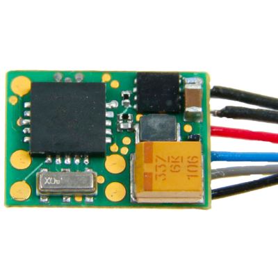
Micro Sound
Uhlenbrock 32616 microSUSI
Very small IntelliSound module for restricted installation spaces.
View Product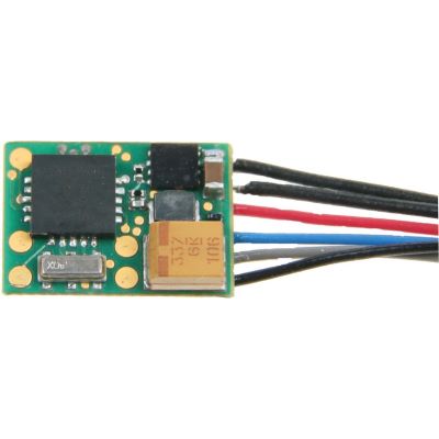
Electric Locomotive
Uhlenbrock 32614 Electric Universal
Universal sound project for electric traction vehicles.
View Product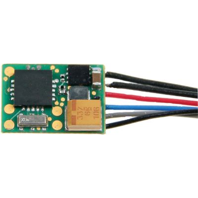
Diesel Locomotive
Uhlenbrock 32614 Diesel Universal
Universal diesel sound module with function mapping.
View Product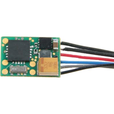
Gauge TT
Uhlenbrock 32610 IntelliSound 6
Programmable sound module with a SUSI interface.
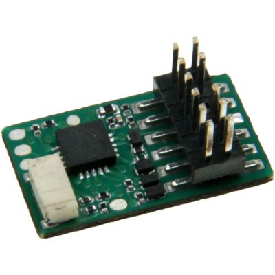
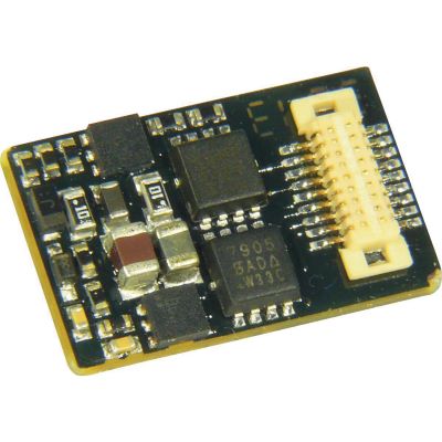
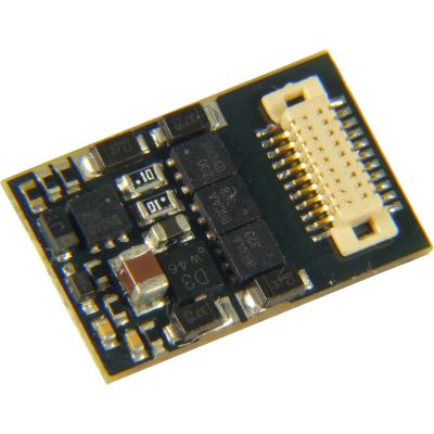
View ProductN, TT, H0e and H0m
Locomotive and Sound Decoders for Compact Scales
These products combine compact vehicle connections with SUSI or microSUSI functionality.
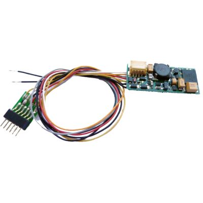
NEM 651
Uhlenbrock 33310 IntelliSound 6
Compact mini decoder for individual sound projects.
View Product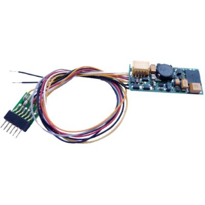
Sound Project
Uhlenbrock 33314 IntelliSound 6
Six-pin mini decoder with a prepared sound project.
View Product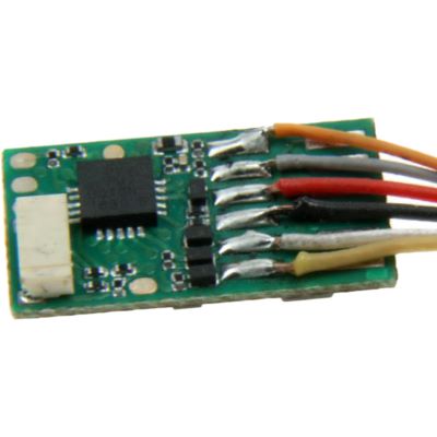
Gauge H0 and Modern Plug-In Systems
Decoders with SUSI via Next18, PluX and 21MTC
On these decoders, logic-level outputs or interface contacts may be used for SUSI functions.
Next18
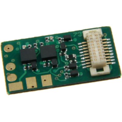
Uhlenbrock 73236 ID2
Next18 locomotive decoder with SUSI and LISSY functionality.
View Product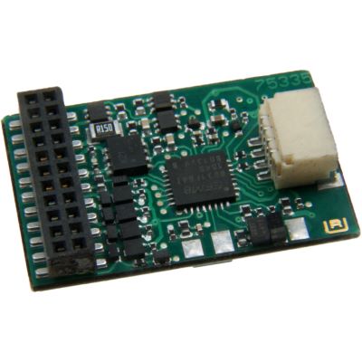
21MTC
Uhlenbrock 75335 ID2
21MTC decoder with alternatively assignable SUSI functionality.
View Product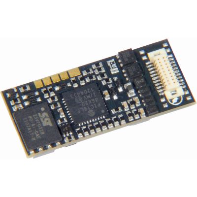
Next18 Sound
ZIMO MX658N18
Sound decoder with alternatively assignable SUSI connections.
View Product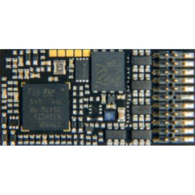
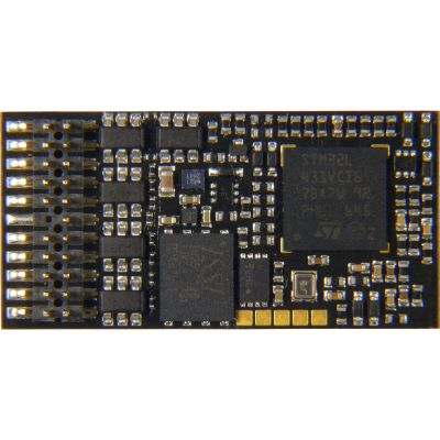
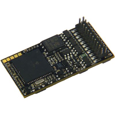
PluX22
ZIMO MX645P22
Sound decoder with SUSI, RailCom and an energy-storage connection.
View Product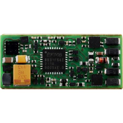
NEM 652
Uhlenbrock 34720 IntelliSound 7
Programmable sound decoder with an eight-pin connection.
View Product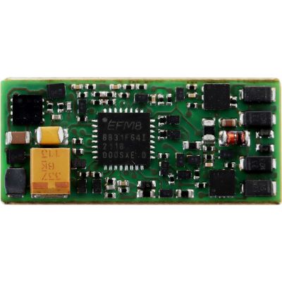
PluX22
Uhlenbrock 34760 IntelliSound 7
Blank PluX22 sound decoder for individual projects.
View ProductWorkshop, Adapters and Large-Scale Models
Program, Connect and Expand SUSI with More Power
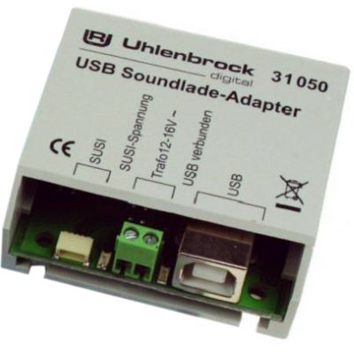
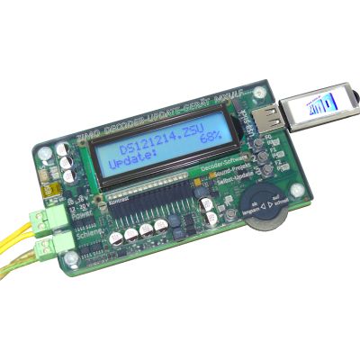
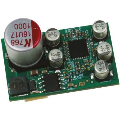
Adapters and loading devices simplify conversions and sound maintenance. A particularly powerful module is available for garden railways.
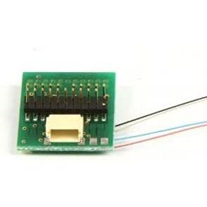
Gauge G
Uhlenbrock 32700 IntelliSound 6
Large-scale module with two powerful audio channels.
View Product
Answers before purchase and installation
Frequently Asked Questions about the SUSI Interface
The instructions for the decoder, expansion module, vehicle and programming device remain binding.
What Does SUSI Mean on a Model Railway?
SUSI stands for Serial User Standard Interface. The internal bus connects a host, usually the locomotive decoder, to sound or function modules.
Is SUSI a Digital Protocol?
No. DCC, Motorola and mfx are transmitted through the track. SUSI operates inside the vehicle between the decoder and expansion module.
Can Every Digital Locomotive Be Retrofitted with SUSI Sound?
Only when the decoder or vehicle circuit board provides a suitable SUSI connection and sufficient space is available for the module, wires and loudspeaker.
What Is the Difference Between SUSI and Next18?
Next18 connects the vehicle circuit board to the locomotive decoder. SUSI connects the installed decoder or another host to additional modules.
How Many SUSI Modules Can Be Connected?
The current rules provide for up to three modules. The host, power supply and software must support multiple-module operation.
What Is microSUSI?
microSUSI is a smaller four-pin version for compact vehicles. Its maximum current capacity is lower than that of classicSUSI.
What Is powerSUSI Used For?
powerSUSI is intended for larger scales and more powerful modules. The version also includes a trigger contact.
Does a SUSI Sound Module Require a Loudspeaker?
Yes. The loudspeaker impedance, power rating, sound enclosure and installation space must suit the module and vehicle.
Can a SUSI Module Produce Sound in Analogue Operation?
Some combinations support speed-dependent analogue sound. This is a product feature and is not automatically included with every interface.
What Is SUSI-BiDi?
SUSI-BiDi adds a return channel to the bus. Compatible modules can respond to host queries with data and confirmations.
Which CVs Belong to SUSI?
The complete reserved range extends from CV 897 to CV 1024. The three modules receive separate ranges beginning at CV 900, 940 and 980.
Can I Simply Reverse a Four-Pin Connector?
No. An incorrect assignment of ground, data, clock and positive power may damage the module or decoder. The pin assignment must be checked.
Technical principles
Plan and Program SUSI Reliably
The current technical principles are described in RCN 600 for the SUSI bus , RCN 601 for SUSI-BiDi and RCN 602 for the configuration variables .
Older sound modules may deviate from current transmission rules. The firmware version, host compatibility and manufacturer approval should therefore be checked before a conversion.
Further introductory information is available in the guides to Digital Model Railways , Choosing a Locomotive Decoder and Choosing a Sound Decoder .
More Knowledge about Sound, Decoders and Digital Model Railways
Discover further guides covering interfaces, digital protocols, vehicle conversions, gauges, layout planning and model railway technology.