Railway Embankment with Ballast Bed
The track lies on an elevated route. The ballast shoulder remains clearly visible, while the earth slope below is covered with grass, weeds and individual bushes.

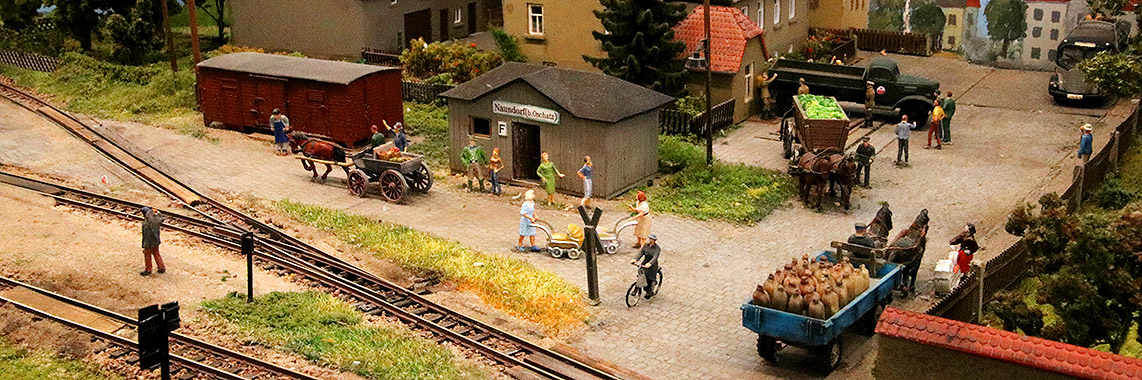
Create believable transitions between track, road and terrain and combine the substructure, soil, ballast, grass fibres, bushes, scree and retaining walls.
A slope is an inclined surface between two different elevations. It occurs beside a railway embankment, in a cutting, next to a road, along a stream bank or at the foot of a mountain. Unlike a retaining wall , it does not overcome the height difference vertically, but through a wider inclined terrain surface.
Building model railway slopes and embankments begins with the supporting terrain form. Foam, rigid foam, ribs, cork, mesh or modelling compound create the incline. Only afterwards are base colour, soil, ballast, grass, scree and vegetation added.
A railway embankment usually has a clearly recognisable crown carrying the track and sloping surfaces on either side. A cutting works in the opposite way: the track lies lower and the slopes rise towards the surrounding terrain. Roadside slopes, riverbanks and natural terrain edges can be more irregular and more heavily vegetated.
The most believable result is created when the slope has an understandable purpose. Drainage channels belong at the bottom, scree collects below steeper sections and bushes tend to grow on ledges and irregular areas rather than being spread evenly across the entire surface.
Shape, material and vegetation depend on whether the railway crosses raised ground, runs through a cutting or simply needs to be integrated naturally into the surrounding scenery.
The track lies on an elevated route. The ballast shoulder remains clearly visible, while the earth slope below is covered with grass, weeds and individual bushes.
The track runs below the surrounding ground. Earth slopes, rock sections, retaining walls or combinations of these elements explain the difference in elevation.
A road requires a level carriageway and gently tapering sides. Guide posts, guardrails, drainage and worn roadside areas complete the scene.
The lowest point lies beside the water or in a ditch. Damp soil, stones, reeds and darker vegetation distinguish this slope from a dry railway embankment.
Rock, scree and low vegetation dominate. Small earth ledges and planted cracks connect the rock structure to the surrounding terrain.
Concrete, walls, stairs, fences and sparse vegetation suit densely developed areas. A retaining wall can replace a slope that would otherwise be too steep.
A slope remains lighter and easier to repair when a stable core carries the form and only a thin outer layer creates the visible terrain surface.
| Material | Strengths | Suitable Use | Pay Attention To |
|---|---|---|---|
| Foam Ramp | lightweight, flexible and noise-reducing | railway embankments, bridge ramps and gradients | test the complete route first and finish the sides afterwards |
| Cork Track Bedding | clean track position and clearly defined ballast shoulders | visible main lines and branch lines | stagger joints and smooth the surface before ballasting |
| Rigid Foam | directly cuttable and dimensionally stable | wide slopes, cuttings and terrain levels | use only compatible adhesives and paints |
| Mesh and Plaster Skin | large free-form terrain with low weight | irregular landscape slopes and riverbanks | apply several thin layers and allow them to dry completely |
| Filler and Texture Paste | clean transitions and directly visible ground texture | wall connections, paths, bare soil and small slopes | avoid unnecessary thickness and protect the rails |
| Retaining Wall and Rock | overcomes major elevation changes in limited space | towns, tunnels, stations and narrow cuttings | explain the transition between wall, rock and natural slope |
Cork and track-bedding products may have a defined side profile for the ballast shoulder. This angle is not automatically suitable for the entire landscape slope. The outer slope can be much wider, more irregular and considerably more vegetated.
The calculator determines the horizontal run of one side and the total width including the upper route. It provides a geometric planning value, not a structural engineering recommendation.
Enter the height difference and route width.
Example: a ratio of 1.5 means 1.5 millimetres of horizontal run for every millimetre of height. If only one slope side is visible, only one lateral run is required instead of the full symmetrical width.
A believable slope rarely consists of one uniform green surface. Visible soil, short base fibres, taller grass, scree and selective vegetation create depth and variation.
Brown, ochre and grey shades prevent bright unfinished patches beneath the vegetation. Paths, drainage channels and dry edges can remain lighter.
A first thin layer of vegetation ties the surface together. Several restrained shades of green usually look calmer and more natural than a completely uniform colour.
Longer fibres, grass tufts and stones work especially well around edges, channels, ledges and less maintained areas.
Vegetation should not block sight lines or signals. Small groups at the bottom or upper edge of the slope look more natural than evenly spaced rows.
Structural materials are often universal. Visible ballast, stones, grass tufts, fences and retaining walls should, however, match the respective model scale.
| Gauge | Scale | Suitable Design | Pay Particular Attention To |
|---|---|---|---|
| Z Gauge | 1:220 | calm surfaces, fine ballast and short fibres | use coarse stones and large bushes only as individual accents |
| N and Nm | 1:160 | long embankments and generous cuttings | grade the grain size and vegetation carefully |
| TT, TTm and TTe | 1:120 | visible ballast shoulders and varied slope vegetation | combine TT slope strips and bedding selectively |
| H0, H0m, H0e and H0f | 1:87 | detailed drainage channels, scree, grass and shrubs | all H0 narrow gauges use the same scenery scale |
| 0, 0m and 0e | usually around 1:45 | strong ground texture and individually placed plants | divide large slopes into transportable sections |
| Gauge 1, Im and Ie | 1:32 | clearly visible soil, roots and larger stones | break up repeated mat textures carefully |
| G Gauge and IIm | prototype-dependent, often around 1:22.5 | robust slopes, natural stone and real plants | plan outdoor drainage, frost resistance and weatherproofing |
Track bedding, terrain skin and vegetation can be combined across manufacturers as long as the scale, material and selected adhesive are compatible.








Filter by gauge, material, project, manufacturer and product group. When this section approaches the viewport, further relevant English product pages are checked directly in the webshop. Unreachable or explicitly archived products are not displayed.
The verified product selection is displayed.
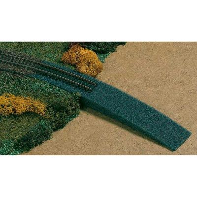
Flexible foam ramp for bridges and elevated track routes.
View Product →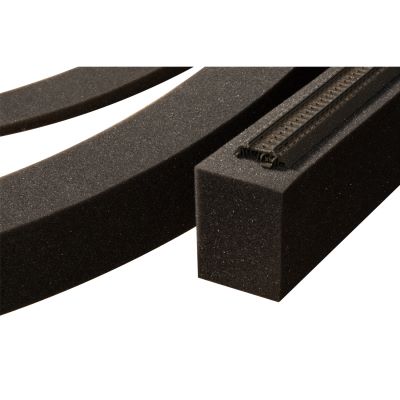
Four flexible segments for longer elevated routes.
View Product →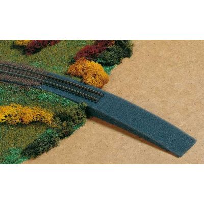
Flexible TT ramp for gradients and bridge approaches.
View Product →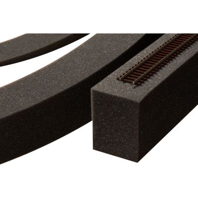
Flexible route extension for long TT ramps.
View Product →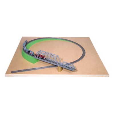
Flexible route core for an individually designed slope.
View Product →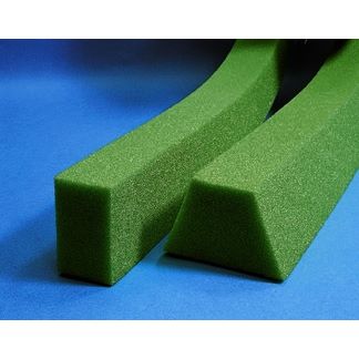
Flexible foundation for a gently elevated route.
View Product →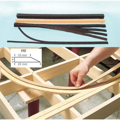
Flexible track base with bevelled side surfaces.
View Product →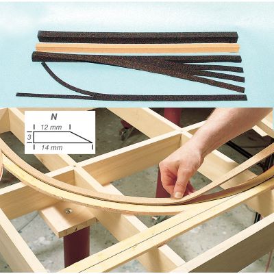
Flexible bedding for straight and curved N-gauge routes.
View Product →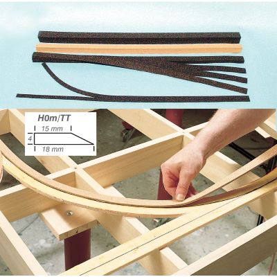
Track bedding for TT and metre-gauge H0 scenery.
View Product →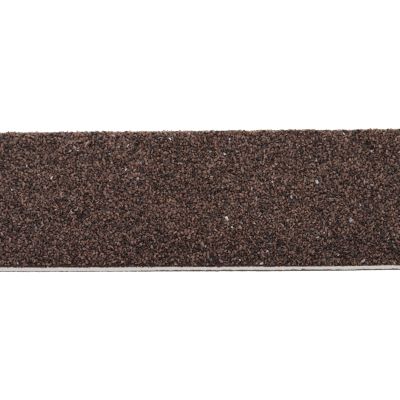
Side finishing strip for dark TT track bedding.
View Product →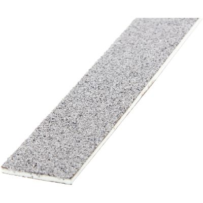
Grey finishing strip for track bedding, turnouts and repairs.
View Product →
Tool for forming a consistent ballast bed profile.
View Product →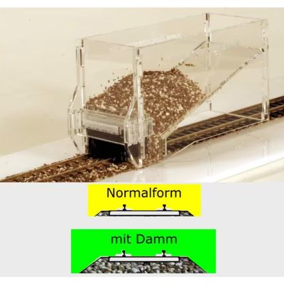
Embankment-profile tool for Märklin K and C Track.
View Product →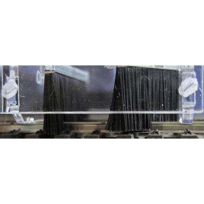
Removes excess ballast from the track area.
View Product →
Soil, clay and sand textures for natural slope surfaces.
View Product →
Smooth terrain skin for transitions, paths and track routes.
View Product →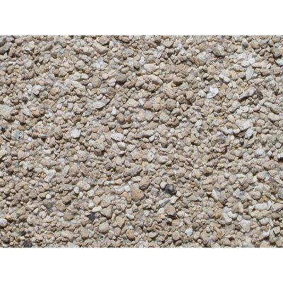
Fine stones for drainage channels, rock bases and embankments.
View Product →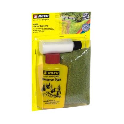
Beginner package for applying upright grass fibres.
View Product →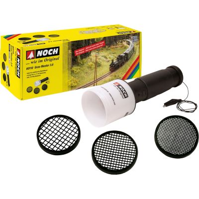
Electrostatic grass applicator for short and long fibres.
View Product →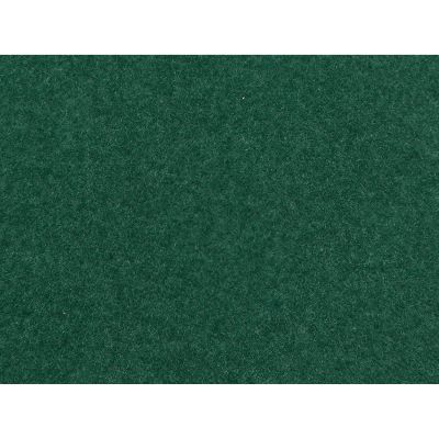
Dark base vegetation for damp and richly green surfaces.
View Product →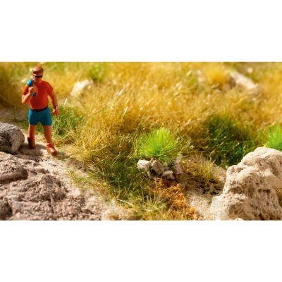
Ready-made accents combining fibres, scatter and small stones.
View Product →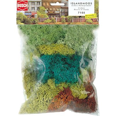
Shapeable natural material for bushes, hedges and undergrowth.
View Product →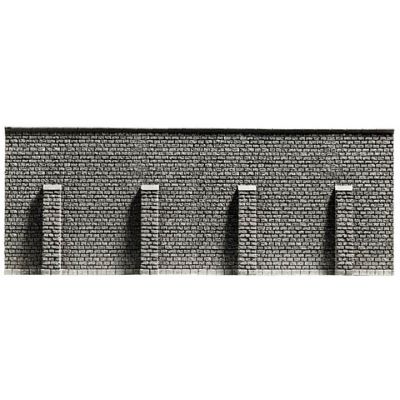
Stone wall for narrow cuttings and changes in terrain height.
View Product →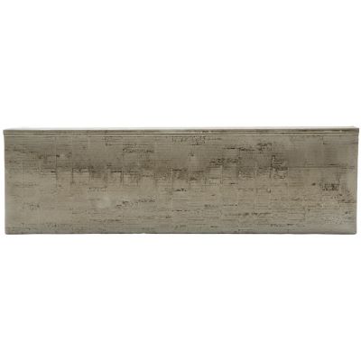
Technical retaining structure for modern railway and road slopes.
View Product →Select the embankment core or terrain form first, followed by soil, ballast, grass, bushes and, where required, a wall or railing.
Cork, railway embankment ramps and side profiles.
Track bed, ballast shoulder and embankment surface.
Base vegetation, wild grass and irregular slope surfaces.
Soil, sand, scree, forest floor and rural paths.
Shrub groups for slope bottoms, edges and rock cracks.
Retaining structures and bases for steep terrain transitions.
Terrain skin and transitions between the railway route and slope.
Protection for paths, roads and upper slope edges.
This construction sequence keeps the track and railway technology clear first and adds delicate vegetation only after all wet construction work has been completed.
Draw the route width, slope bottom, drainage channels and adjacent structures onto the base.
Approve turnouts, curves and hidden sections before terrain construction begins.
Work with the large shapes first and judge the outline from the normal viewing position.
The ballast profile remains clearly visible while the outer slope transitions gently into the surrounding terrain.
Completely connect transitions to walls, roads, rocks and the layout base.
Keep channels and bare soil visible before applying grass fibres.
Mix colours and fibre heights in sections instead of distributing them uniformly.
Keep tracks, signals, paths and maintenance access unobstructed.
A slope that has exactly the same angle everywhere and is completely covered in green looks artificial. Small ledges, bare soil, scree, varied fibres and changing inclines create a more natural appearance.
On a railway embankment, vegetation must not grow up to the rail heads or movable turnout parts. Drainage channels, cable ducts and maintenance paths also need clearly visible unobstructed areas.
Very steep slopes often need a visible explanation: rock, retaining walls, gabions or another technical retaining structure. Without such an element, an almost vertical earth slope rarely appears convincing.
Keep vehicle overhang and lateral cleaning access completely clear.
Combine soil, beige, dark green and dry fibres.
Concentrate stones below edges, in drainage channels and at the bottom of the slope.
Protect technical areas during all adhesive and scatter-material work.
Test adhesive, paint, foam and filler together before working on a large section of the layout. The processing instructions and safety information supplied by the respective manufacturer remain authoritative.
These answers help with railway embankments, cuttings, material selection, gauges, vegetation and a safe track environment.
The railway embankment is the complete elevated route. Its inclined side surfaces are the slopes. Slopes can also occur beside roads, waterways and cuttings.
Suitable materials include rigid foam, flexible foam, cork, ribs, mesh and modelling compound. A lightweight core combined with a thin visible terrain skin is often the most versatile solution.
There is no single correct angle for every scene. Broad earth and grass slopes generally look more natural. Very steep areas are better explained with rock or a retaining wall.
The edge forms a regular ballast-bed slope immediately beside the track. The outer landscape slope can be considerably flatter and more irregular.
Flexible cork or foam strips follow the track curve. Alternatively, build the substructure from short segments and connect them afterwards with filler or mesh.
First colour the ground. Then add short base fibres, longer wild grass, individual tufts, scree and selectively positioned bushes.
Short, fine fibres are generally most convincing in Z and N. Longer fibres can be used selectively to represent tall wild grass or neglected areas.
Paint the entire surface with earth, ochre or grey shades before adding vegetation. Any remaining gaps then look like natural ground rather than unfinished scenery material.
A retaining wall saves space and is suitable for narrow urban, station and tunnel areas. A natural slope needs more width but creates a softer landscape transition.
Keep rails, turnouts, signals and cable ducts clear. Remove loose fibres and stones before railway operation resumes.
Yes. H0, H0m, H0e and H0f all use 1:87 scenery scale. Track-bed width and vehicle profile nevertheless differ between the individual model track gauges.
A short straight railway embankment on a test board is a good starting point. It allows the substructure, filler, ballast, grass fibres and bushes to be tested together without risking a finished layout.
Define the height and width, test the railway route and then build soil, ballast, grass, scree and vegetation in several layers.
Open the Main Model Railway Guide
Content reviewed on 16 August 2026. Product dimensions and the processing and safety instructions supplied by the respective manufacturer remain authoritative.