Railway Cutting
One or two walls guide the track through higher ground. Buttresses, cable ducts, signals and dirty wall bases make the cutting operationally believable.

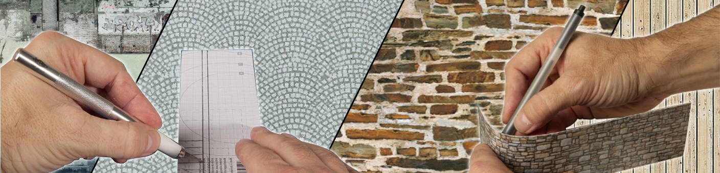
Plan retaining walls for changes in terrain height, railway embankments, roads, tunnel portals, urban terraces and mountain routes and choose materials, textures and weathering to suit the model railway gauge.
On the prototype, a retaining wall holds back soil, rock or a higher traffic surface. On a model railway, it explains why a track, road, station or building can lie directly beside a lower area of terrain. It therefore replaces a broad natural slope and creates additional usable levels within a limited space.
Building retaining walls for a model railway involves more than simply gluing a textured panel in place. Height, alignment, wall coping, buttresses, drainage, colouring and the transition into the surrounding terrain all need to work together. The wall should look like part of the railway route rather than a vertical decoration.
The visible wall generally does not have to carry real earth pressure in the model. The supporting terrain form is created from wood, rigid foam, ribs or another stable substructure. The retaining wall, wall panel or arcade element then forms the scale surface.
Walls look especially convincing when they have a clear purpose. They may retain a railway cutting, carry a road above the track, form an abutment beside a bridge or support a hillside station. Small drainage outlets, water stains, scree and plants additionally show how the structure is used and has aged over time.
Walls are especially useful wherever a natural slope would consume too much space. Their alignment should always follow the terrain and the railway operation being represented.
One or two walls guide the track through higher ground. Buttresses, cable ducts, signals and dirty wall bases make the cutting operationally believable.
The retaining wall visually supports a higher railway route. Scree and low vegetation connect the bottom of the wall, ballast bed and surrounding landscape.
A wall permits compact road alignments, parking areas or houses above the railway. Railings and pavements should be planned together with the wall coping.
Retaining walls create level areas for a station building, platforms, goods shed and forecourt without squeezing the entire station between broad slopes.
Wing walls guide the terrain towards a portal or abutment. Wall texture, rock and structure should share a coherent regional material character.
Concrete walls suit commercial and modern infrastructure, while natural stone is especially appropriate for mountain and narrow-gauge railways. Arcades can additionally suggest workshops or storage spaces.
Ready-made rigid-foam walls quickly provide a three-dimensional surface. Wall panels and printed card are particularly useful for custom lengths, curves and large scratch-built projects.
| Construction Type | Strengths | Typical Use | Pay Attention To |
|---|---|---|---|
| Textured Rigid Foam | three-dimensional stone texture, low weight and easy processing | ready-made retaining walls, arcades and long hillside walls | cut cleanly with a sharp tool and recolour exposed cut surfaces |
| Embossed Plastic Sheet | thin, flexible and suitable for curved bases | large scratch-built walls, tunnel interiors and façades | base joints and sheet transitions must not show through |
| Card and Printed Card Sheet | very easy to cut and particularly suitable for small scales | N, Z, background walls and flat surfaces | avoid moisture and seal cut edges with matching colour |
| Arcade Wall | breaks up long wall surfaces and creates architectural depth | urban railway, stations, viaducts and road retaining structures | plan arch spacing, pier width and connecting sections consistently |
| Concrete Retaining Wall | clear technical form for modern railway and industrial scenes | main lines, towns, modern construction, depots and underpasses | use formwork joints, repairs and water stains sparingly |
| Scratch-Built Filler or Plaster Wall | custom curves, heights and irregular wall alignments | special shapes, large scales and heavily customised terrain | engrave the texture consistently and allow the material to dry fully |
A thin panel or printed decorative sheet should be mounted on a stable, flat base. This keeps the wall straight while allowing the actual terrain form to be supported independently.
Measure the alignment directly on the layout substructure. Curves, stepped walls and angled ends create additional waste. Long walls look better when joints coincide with buttresses, terrain edges or arcade arches.
Enter the project length and element length.
The result is a material-planning aid. Arcade spacing, end pieces, buttresses, changes in height and curved sections may require additional elements.
A wall looks believable when its weathering follows its location. Moisture collects beneath outlets, soil and scree gather at the bottom and upper edges may fade more strongly.
Coping stones, concrete slabs or railings protect and divide the upper edge. Unfinished foam or card edges should never remain visible.
Buttresses, offsets and stairs break up long surfaces. Their spacing may be regular but should respond logically to the terrain and structure.
Small drainage openings or pipes are convincing prototype details. Dark, greenish or chalky marks can be added sparingly beneath them.
A thin wash emphasises recessed joints. Individual stones can receive slightly different grey, beige or brown tones without creating a colourful checkerboard appearance.
Fine material gathers in channels and corners, while larger fragments are more plausible beneath damaged areas. The track ballast bed should remain clearly defined.
Moss, grass tufts and small shrubs preferably grow in damp joints, at the wall base and on horizontal ledges. Vegetation should not cover every surface evenly.
H0, TT, N and Z offer a particularly large selection of ready-made wall products. Large scales can additionally make good use of textured panels and individually constructed walls.
| Gauge | Scale | Suitable Wall Solution | Design Note |
|---|---|---|---|
| Z Gauge | 1:220 | fine arcades, card panels and small facing elements | use very small stones and restrained joint detailing |
| N and Nm | 1:160 | ready-made retaining and arcade walls plus fine wall panels | divide long walls with small buttresses and subtle colour changes |
| TT, TTm and TTe | 1:120 | rigid-foam walls, arcade elements and scratch-building panels | check H0/TT products according to the actual stone texture |
| H0, H0m, H0e and H0f | 1:87 | widest selection of stone, concrete, arcade and segment walls | all H0 narrow gauges use the same scenery scale |
| Gauge 0, 0m and 0e | usually around 1:45 | large textured panels, plaster and individually built buttresses | detail joints, coping stones and drainage outlets clearly |
| Gauge 1, Im and Ie | 1:32 | three-dimensional panels and stable segmented scratch-building | avoid obvious repetition of identical textures |
| G Gauge and IIm | prototype-dependent, often around 1:22.5 | robust scratch-built structures and outdoor-suitable materials | consider drainage, frost and weather resistance outdoors |
Ready-made walls, arcades, decorative panels and scratch-building materials from different manufacturers can be combined when scale, stone size and colour effect are compatible.








Filter by gauge, material, construction style, manufacturer, application and product group. When this section approaches the viewport, additional products from the complete wall-panel category are loaded and checked for reachable, non-archived English product pages.
The verified product selection is displayed.
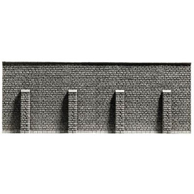
Hand-coloured stone retaining wall for slopes, railway routes and building levels.
View Product →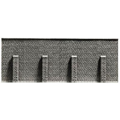
Continuous element for larger changes in terrain height.
View Product →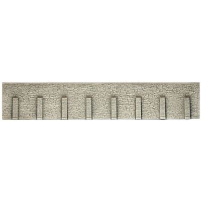
Long rigid-foam element for mountain and rural slopes.
View Product →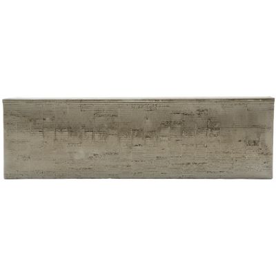
Technical wall for urban areas, railway routes and industry.
View Product →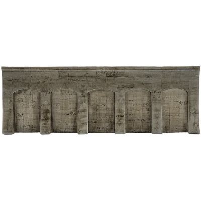
Structured concrete wall for modern infrastructure.
View Product →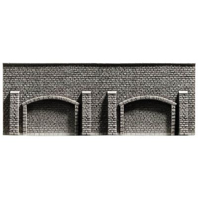
Stone arcades for stations, towns and hillside scenes.
View Product →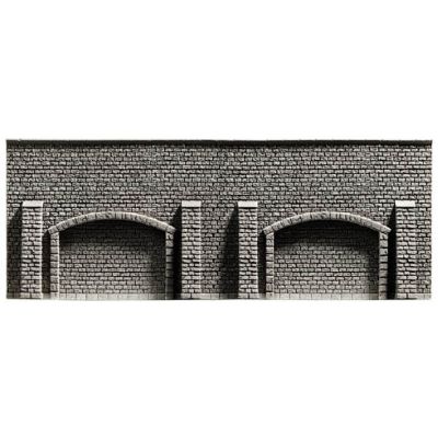
Long structured wall for larger urban and railway scenes.
View Product →
Open arches for viaducts, urban walls and station scenes.
View Product →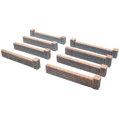
Multi-part wall with buttresses for flexible alignments.
View Product →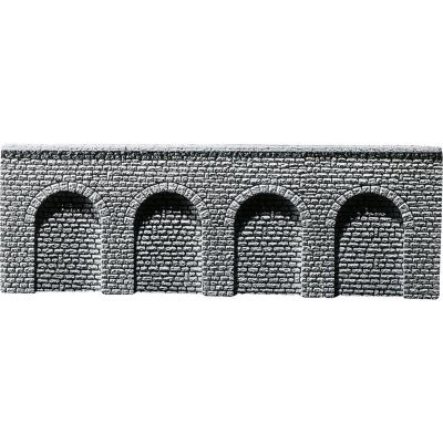
Ashlar-stone arches for custom walls and viaducts.
View Product →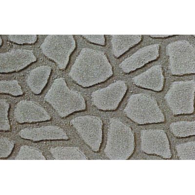
Two large panels for custom retaining walls.
View Product →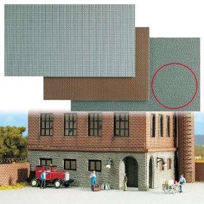
Flexible surface for straight and curved scratch-built walls.
View Product →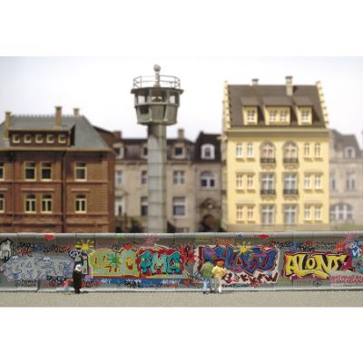
Technical boundary for industrial and modern urban scenes.
View Product →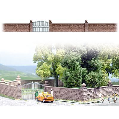
Wall, posts and gate for a property or industrial yard.
View Product →
Stone wall for TT embankments, roads and urban slopes.
View Product →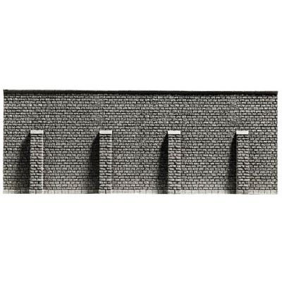
Large TT element for longer railway and road sections.
View Product →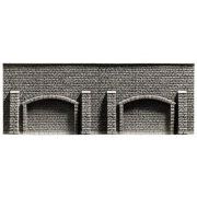
Compact stone arcades for stations and urban scenes.
View Product →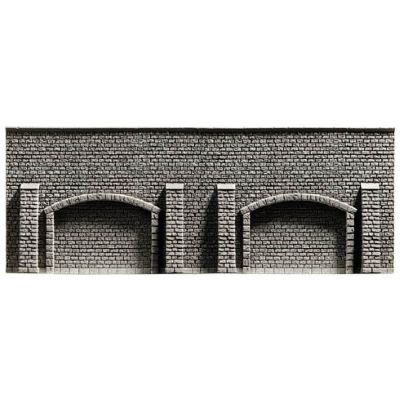
Long structured wall section for larger TT scenes.
View Product →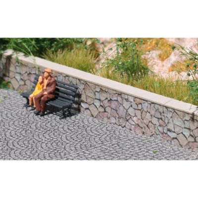
Multi-part kit for flexible TT wall alignments.
View Product →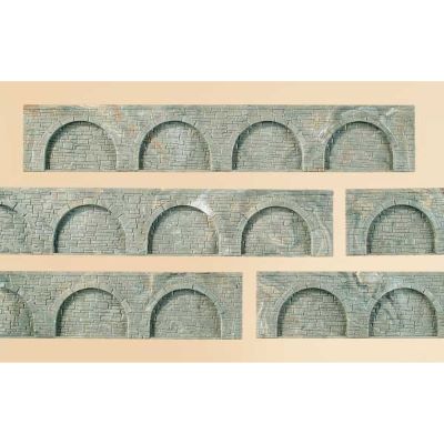
Six arches for scratch-built retaining and bridge walls.
View Product →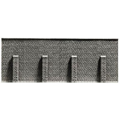
Compact element for slopes and urban scenes in N gauge.
View Product →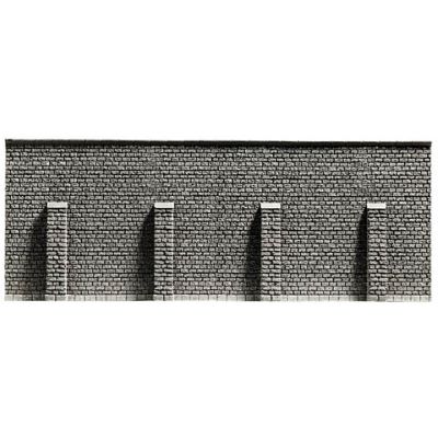
Continuous rigid-foam element for long N-gauge routes.
View Product →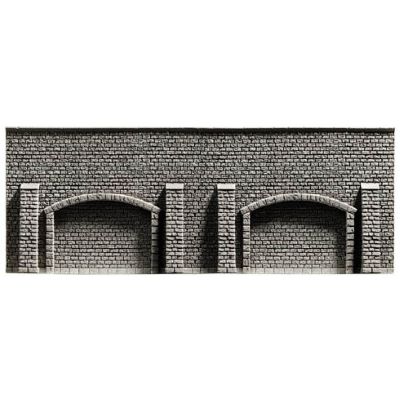
Small arcades for towns, stations and railway cuttings.
View Product →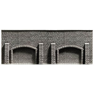
Long arcade sequence for larger N-gauge projects.
View Product →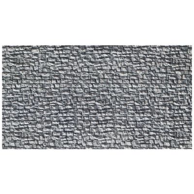
Cut-to-size panel for individual small retaining walls.
View Product →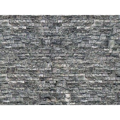
Fine stone texture for individual N-gauge retaining walls.
View Product →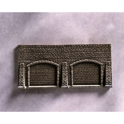
Fine rigid-foam element for compact Z-gauge scenes.
View Product →Choose the height, alignment and scale first. Then add buttresses, wall coping, colour, scree and vegetation.
Retaining walls, wall panels, printed card and textured foils.
Shape transitions, wall bases and individual scratch-built structures.
Detail wall bases, drainage areas and surrounding slopes.
Colour joints, water stains, repairs and traces of moss.
Connect wing walls and tunnel entrances naturally to the hillside.
Plan abutments, arcades and retaining walls together.
Add elevated roads, pavements and railings.
Material-compatible bonding for panels, foam and terrain.
This sequence separates the stable substructure, visible wall surface and fine detailing so cuts, joints and terrain transitions remain controllable.
Measure the height, length, curve and adjacent structures directly on the layout.
Wood, rigid foam or ribs carry the terrain independently from the visible retaining wall.
Choose natural stone, ashlar, brick or concrete to match the other architecture on the layout.
Test all segments before gluing and finish cut surfaces cleanly.
Press the wall evenly into place without deforming fine textures or delicate arcade elements.
Coping stones, railings, buttresses and stairs divide the wall and explain how it is used.
Thin layers preserve the texture and visually connect several wall elements.
Soften the transition while keeping tracks and drainage areas unobstructed.
A long wall without buttresses, steps or colour variation quickly looks like a backdrop. Divide larger surfaces and place product joints at architecturally plausible points.
Another common problem is a visible raw top edge. Wall coping, a pavement, vegetation or a railing hides the substructure and turns the vertical surface into a complete structure.
Paint should not clog fine detail. Work with thin layers and test washes and adhesives on a scrap piece first. Cutting tools, heat and adhesives must only be used in accordance with the manufacturer’s safety instructions.
Thin panels require a flat and permanently stable backing.
Hide joints at buttresses, arcades, stairs or groups of vegetation.
Coarse H0 textures look oversized on an N- or Z-gauge layout.
Moisture, dirt and vegetation follow edges, outlets and joints.
A road or railway route on the upper level requires sufficient clearance from the edge. Vehicles, overhead wiring and railings must not later project awkwardly beyond the visible wall face.
These answers help with selection, cutting, curved walls, arcades, drainage and scale-appropriate design.
It replaces a broad slope and allows several terrain levels to be represented within a small area. Typical applications include railway cuttings, roads, hillside stations and tunnel portals.
Textured rigid foam is lightweight and three-dimensional, plastic panels are flexible and card is easy to cut precisely. The best choice depends on the shape, size and model scale.
Many rigid-foam elements can be cut with a sharp modelling knife or fine saw. The processing instructions supplied by the respective manufacturer remain authoritative.
Flexible wall panels are particularly suitable. Rigid elements can be assembled from short sections and their joints concealed with buttresses or vegetation.
The height depends on the terrain difference and the scale. Very high walls should be divided by buttresses, steps, arcades or a second terrain level.
Arcades suit urban railways, stations, viaducts and long retaining walls. They divide large surfaces and can suggest usable spaces behind the arches.
Concrete walls, clear formwork joints and technical railings are especially suitable. Subtle dirt and repair marks prevent the surface from looking too uniform.
H0m and H0e use the same 1:87 scenery scale as H0. H0 walls are therefore suitable from a scale point of view, although they should not look unnecessarily monumental beside a small mountain railway.
Place the joint at a buttress, wall step or arcade. Fine filler, paint, scree and vegetation can then blend the remaining transition into the structure.
Small outlets are a realistic prototype detail. Water or lime stains beneath them should be added sparingly and positioned according to the surrounding terrain drainage.
A thin dark wash emphasises the joints. Slightly varied stones, highlighted edges, moisture near the base and a little moss add depth without covering the texture.
Build a short straight wall section on a test board first. This shows how cutting, adhesive, joint colour and vegetation work together before the technique is applied to the layout.
Match the length, height, stone texture and material to the model railway gauge and then add coping, buttresses, weathering and vegetation.
Open the Main Model Railway Guide
Content reviewed on 16 August 2026. Product dimensions, material specifications and the processing and safety instructions supplied by the respective manufacturer remain authoritative.