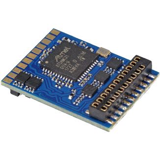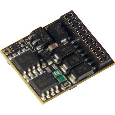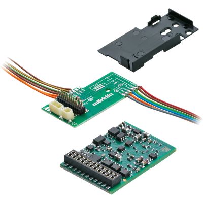





NEM 651
Six contacts are arranged in a straight row. The decoder may plug in directly, at an angle or via a cable.
Typical For
Gauges N, TT and older compact H0 vehicles.

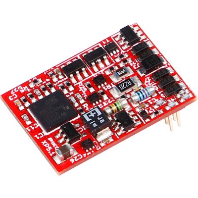
NEM 651, NEM 652, Next18, PluX22 and 21MTC look different and are not electrically interchangeable. This comparison shows which interfaces are used in which gauges and what to consider when installing a decoder.
A decoder interface connects the vehicle circuit board to a locomotive, sound or function decoder. It carries track voltage, motor connections and lighting outputs and, depending on the version, additional functions, loudspeaker connections, energy storage or data lines.
The interface does not determine the digital protocol. A PluX22 interface, for example, can be fitted with a DCC-only decoder or a multiprotocol decoder. The connector, pin assignment, motor output, installation space and digital format must all be compatible.
In a locomotive with an interface, the analogue blanking plug is removed and the correct decoder is inserted. However, decoders with the same number of contacts are not automatically compatible. Next18, PluX and 21MTC differ fundamentally in design, installation orientation and pin assignment.
A vehicle without an interface can also be digitised. The decoder is then connected using wires. During this conversion, the motor, current pickup and lighting must be fully checked and electrically isolated where required.
The schematic illustrations provide an initial guide. The vehicle instructions and markings on the locomotive circuit board remain authoritative.
Six contacts are arranged in a straight row. The decoder may plug in directly, at an angle or via a cable.
Gauges N, TT and older compact H0 vehicles.
Eight pins are arranged in two rows. A marking normally indicates the position of pin 1.
Older and simply equipped H0 locomotives.
A very small enclosed connector with contacts on both sides. Next18S accommodates sound applications.
Gauges N, TT, H0e and compact H0 vehicles.
The pins are located on the underside of the decoder. The vehicle circuit board has the matching socket strip.
TT and H0 vehicles with different levels of equipment.
The pins are normally located on the vehicle circuit board. The decoder is fitted over them using its socket strip.
Feature-rich H0 models and many Märklin conversions.
A compact newer interface with 24 electrical contacts and additional guide positions.
New compact vehicles in N, TT and small H0 gauges.
| Interface | Contacts | Identifying Feature | Typical Gauges | Strengths | Important Considerations |
|---|---|---|---|---|---|
| Wires | Depending on the decoder | Coloured connecting wires without a vehicle connector | Z to G | Flexible for older vehicles | Correctly isolate the motor and lighting |
| NEM 651 | 6 | One straight row of pins | N, TT and older small H0 | Compact and simple | Distinguish direct, angled and wired versions |
| NEM 652 | 8 | Two rows of four pins | Mainly H0 | Widely used classic standard | Check pin 1 and the available decoder height |
| Next18 | 18 | Small enclosed connector | N, TT, H0e and small H0 | Compact and more versatile than NEM 651 | Check the installation space and output assignment |
| Next18S | 18 | Mechanically closely related to Next18 | N, TT and small H0 sound models | Sound connections in a compact design | Do not replace it with Next18 without checking |
| PluX12 | 12 | Two short rows of pins on the decoder | TT and small H0 | Compact entry into the PluX family | Fewer functions than larger PluX versions |
| PluX16 | 16 | Two rows of pins on the decoder | TT, H0 and sound conversions | Good compromise between size and functions | Distinguish PluX16 and PluX16S precisely |
| PluX22 | 22 positions | Long two-row pin strip on the decoder | Mainly H0 | Numerous lighting, sound and auxiliary functions | Do not confuse it with 21MTC |
| 21MTC | 21 contacts in 22 positions | Pins on the locomotive board, sockets on the decoder | H0 and some Gauge 0 models | Numerous functions, sound and energy-storage connections | Distinguish logic-level and amplified outputs |
| E24 | 24 plus guide positions | Very small enclosed connector | N, TT and small H0 | Compact with numerous possible outputs | Not yet common in every vehicle |
| PluG | Depending on the version, 16 to 44 | Multi-part large pin headers | 0, 1, G and IIm | High currents and numerous large-scale functions | Document the vehicle and decoder pin assignments |
NEM 651 has six pins and covers the motor, current pickup and driving lights. Next18 provides more contacts for additional functions and requires a matching enclosed socket.
NEM 652 is a classic eight-pin connection. PluX22 provides considerably more connections for lighting, sound, energy storage and auxiliary functions.
With PluX, the pins are on the decoder. With 21MTC, the vehicle circuit board carries the pins. A mechanically improvised conversion is not permitted without a suitable adapter board.
Both variants use a compact 18-pin connection. Next18S, however, accommodates sound connections and a larger intended installation space.
The PluX family uses a common basic principle. Smaller decoders cannot, however, provide all functions intended on a larger vehicle socket.
E24 was developed for small installation spaces and a large range of functions. Decoders, adapters and vehicles must be explicitly designed for E24.
Direct decoders plug straight into a vehicle socket. With NEM 651 in particular, distinguish between straight and angled pin arrangements.
Free space beside and above the socket.
A cable between decoder and connector makes positioning easier but requires additional space and must not be trapped between the body and chassis.
Cable length, bending radius and secure mounting.
SUSI is an auxiliary connection for sound or function modules. It does not replace the main connection between the vehicle circuit board and locomotive decoder.
Support by the decoder and auxiliary module.
Some vehicles use proprietary plug-in boards or decoder shapes. A standard decoder can then only be used with an expressly compatible adapter board.
The locomotive product number and production series.
Adapters can change the mechanical connection. They do not automatically resolve differences in output type, current rating or function assignment.
The complete pin assignment of the adapter used.
PluG is intended for large vehicles with high currents and extensive equipment. Its size can vary according to the required number of contacts.
Motor current, smoke, sound and vehicle documentation.
Wires, NEM 651, Next18 and increasingly E24 are particularly space-saving. Decoder height and free space above the circuit board are decisive.
Micro and nano decoders with low motor output.
NEM 651, Next18, PluX12 and PluX16 are common solutions. Some modern TT vehicles already use PluX22.
Compact design with several lighting functions.
NEM 652, Next18, PluX16, PluX22 and 21MTC are widely used. The production year and manufacturer determine the actual version installed.
Wide choice of locomotive, sound and function decoders.
21MTC, larger PluX solutions, PluG or free wiring may be used. The motor current must be checked independently of the interface.
Numerous functions and powerful sound equipment.
Large-scale decoders are often connected using screw terminals, wires, manufacturer-specific boards or PluG.
Several motors, smoke generators and high total currents.
The gauge only provides an initial indication. The socket actually installed, locomotive circuit board and mechanically available installation space are always decisive.
Open the locomotive, photograph and measure it, and compare the instructions.
The motor, current pickup, gearbox and lighting must operate without faults.
Release clips, screws, wires and body components according to the instructions.
Photograph the socket, blanking plug, pin marking and installation space.
Never tilt it, press on components or work while the command station is switched on.
Read the decoder address and test the motor and lighting first.
Check auxiliary outputs, sound, energy storage and direction-dependent lighting.
Equal or similar contact counts do not mean that the interfaces are identical.
The pin positions and electrical assignments are different.
The sound version and intended installation situation must be considered.
With connectors that are not polarised, an incorrect orientation can damage functions.
The correct interface does not guarantee sufficient installation space.
Unassigned or differently implemented functions remain problematic despite an adapter.
The product selection includes locomotive, sound and function decoders for different gauges. Before ordering, compare the interface, decoder dimensions, motor current and function assignment with the vehicle.
Direct connectors and flexible wired versions for small installation spaces and older vehicle circuit boards.
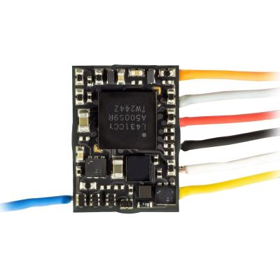
Extremely compact direct decoder with six pins.
View Product →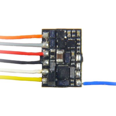
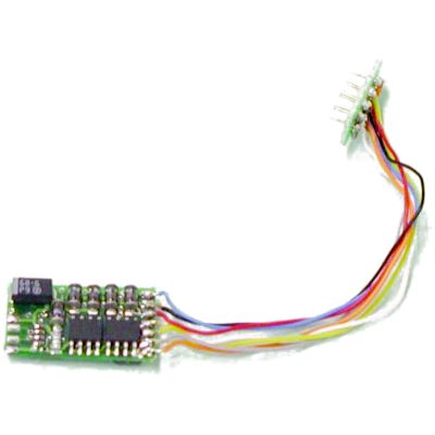
Subminiature version for vehicles without a plug-in socket.
View Product →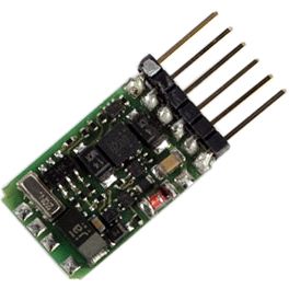
Compact DCC decoder for small locomotives.
View Product →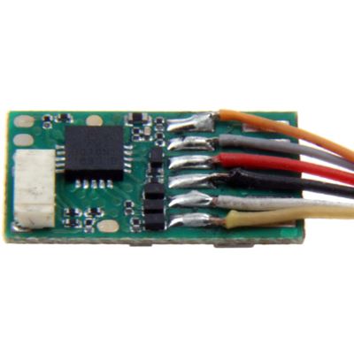
Flexible positioning beside the vehicle socket.
View Product →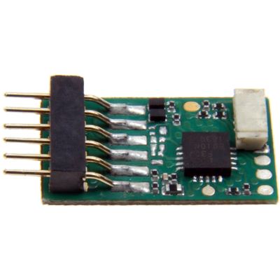
For lighting and auxiliary functions without motor control.
View Product →Locomotive and function decoders for numerous older and simply equipped H0 vehicles.
Classic eight-pin decoder for H0 vehicles.
View Product →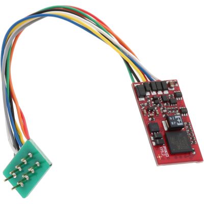
Multiprotocol version for classic eight-pin sockets.
View Product →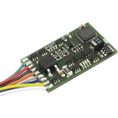
Reliable standard decoder with ABC braking.
View Product →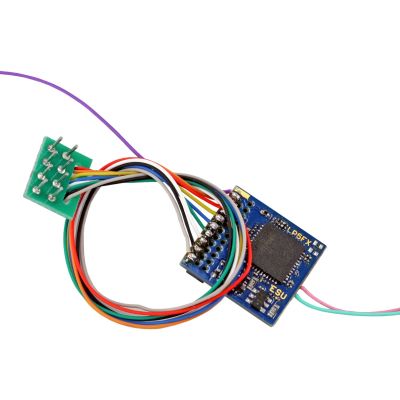
For control cars and vehicles without a traction motor.
View Product →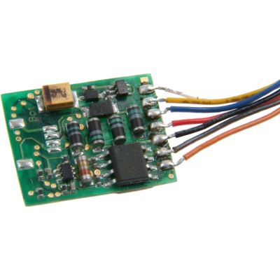
Modern eight-pin decoder with feedback functions.
View Product →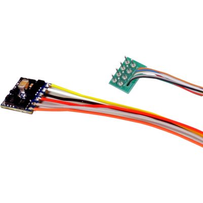
Small DCC version for limited installation space.
View Product →Locomotive, function and sound decoders for Gauge N, TT and small H0 vehicles.
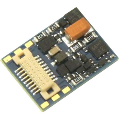
Compact multiprotocol decoder.
View Product →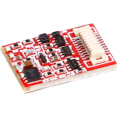
For control cars and lighting circuit boards.
View Product →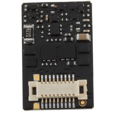
For selected Tillig H0e vehicles.
View Product →
Compact sound decoder for small vehicles.
View Product →Modern plug-in decoders with different function ranges for TT, H0 and compact sound projects.
Feature-rich decoder for modern H0 locomotives.
View Product →
DCC locomotive decoder for PluX22 vehicle boards.
View Product →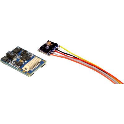
Small PluX version for N and TT.
View Product →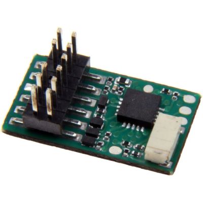
Compact plug-in version for suitable TT locomotives.
View Product →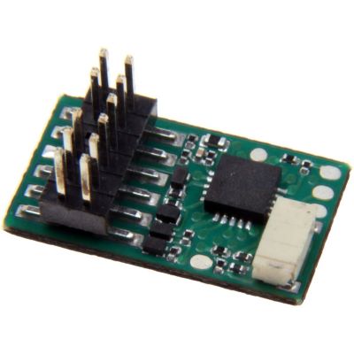
Decoder for compatible TT vehicle circuit boards.
View Product →
PluX12 locomotive decoder for compact vehicles.
View Product →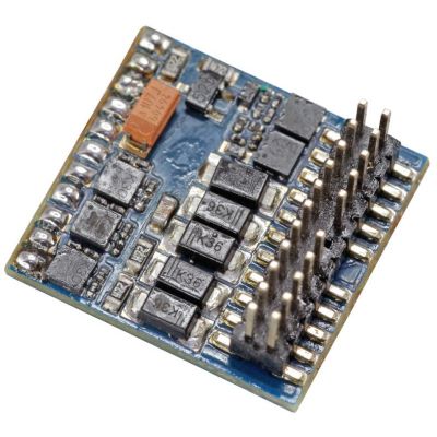
Numerous outputs for control cars and function models.
View Product →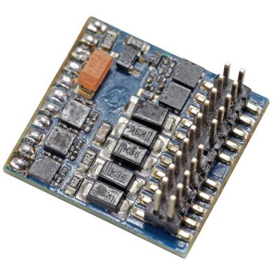
DCC function decoder with extensive mapping.
View Product →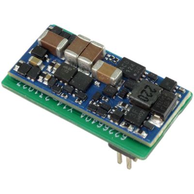
Compact sound decoder for N and TT.
View Product →Decoders with a socket strip for locomotive circuit boards fitted with contact pins.
Check the instructions, packaging and circuit board actually installed. The interface may differ between production series.
Contact count is only one clue. Connector shape, pin arrangement, installation orientation and markings must also match.
No. They have different mechanical and electrical assignments and must not be connected directly.
This may be mechanically possible with a standards-compliant configuration. However, not all functions provided by the vehicle board will then be available.
Next18S accommodates sound connections and a larger intended installation space. The vehicle documentation must specify the actual variant.
NEM 651 is a six-pin electrical interface used especially in N, TT and older small H0 vehicles.
NEM 652 is a classic eight-pin interface carrying motor, track pickup, lighting and common positive connections.
Yes. Use a wired decoder. The motor must be electrically isolated from the track pickup and, where applicable, from the chassis.
No. Next18 is also used in TT, H0e and compact H0 vehicles. Gauge alone does not determine the interface.
E24 is a compact newer vehicle interface for small installation spaces with numerous possible function connections.
PluG is an interface for large model railway vehicles with higher current requirements and an extensive range of functions.
No. An adapter can connect connector shapes but cannot automatically compensate for missing contacts, different output types or insufficient current capacity.
The NEM interfaces NEM 651, NEM 652, NEM 658, NEM 660, NEM 662, NEM 663 and NEM 664 were considered.
Content status: 17 July 2026. Check the current vehicle instructions and decoder pin assignment before installation.
The main guide covers locomotive decoders, sound decoders, digital command stations, digitisation, wiring and layout planning.