
Install a decoder and digitise model railway locomotives safely
From identifying the interface to completing the first test run, this guide explains how to choose locomotive, function and sound decoders, install them correctly, hard-wire them and test them on a programming track. It covers Z, N, TT, H0e, H0m, H0, 0, 1 and G gauges.
Step by Step
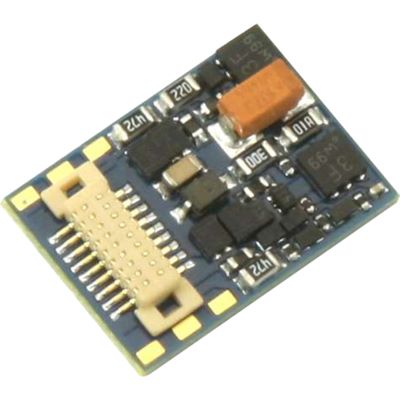
From an analogue model to a digital locomotive
What happens when a decoder is installed?
A locomotive decoder is electrically positioned between the track and the motor. It receives commands from the digital command station, controls speed and direction and switches the lighting or other functions. A sound decoder additionally provides sound playback and controls a loudspeaker.
In a digital-ready locomotive, the factory-fitted blanking plug is removed and replaced with a compatible decoder. This is the simplest form of digitisation. Nevertheless, the interface, installation orientation, decoder dimensions, motor current and digital format must all be checked.
Vehicles without an interface require hard wiring or a suitable adapter board. The track pickups, motor, lighting and auxiliary functions are connected individually. It is especially important that both motor connections are completely isolated from the track connections and from any conductive vehicle frame.
Before conversion, the locomotive should run mechanically faultlessly in analogue operation. A dirty gearbox, stiff motor or poor current pickups will not be repaired by a decoder. These faults may instead cause an overload.






Mechanically and electrically compatible
Which decoder fits my locomotive?
The visible plug design is only one selection criterion. The decoder must also be compatible with the motor, command station, available installation space and required functions.
Direct-plug decoder
The decoder is inserted directly into a prepared interface. This compact solution normally requires no soldering.
Wired plug-in decoder
The plug is connected to the decoder by wires. This allows the circuit board to be mounted flexibly in a free location inside the vehicle.
Hard wiring
Every wire is connected individually. This method requires reliable knowledge of motor isolation and function outputs.
Adapter board
An adapter board adds a modern plug connection and makes future decoder replacement or additional functions easier.
Measure the current before purchasing
The gauge alone does not determine which decoder is required
A small, well-maintained motor may draw very little current, while an older H0 motor may require considerably more. Where possible, briefly measure the current with the motor stalled and observe the decoder manufacturer's specifications.
Plug designs and typical gauges
Identify the decoder interface correctly before installation
The packaging, spare-parts sheet and vehicle instructions provide the most reliable identification. The number of contacts alone does not automatically identify an interface.
| Interface | Identification feature | Typical gauges | Installation note |
|---|---|---|---|
| NEM 651 | Six pins arranged in one row | N, TT, H0e and H0m | Explicitly check pin 1 and the installation orientation |
| NEM 652 | Eight-pin plug with two rows | Mainly H0 | The orange wire normally identifies pin 1 |
| Next18 / Next18-S | Small, flat plug connection | N, TT and small H0 vehicles | Position the decoder straight and without applying pressure |
| PluX16 / PluX22 | Pin header on the decoder with one index pin omitted | TT, H0 and some 0 gauge vehicles | Do not confuse it with 21MTC |
| 21MTC | Socket on the decoder and pins in the vehicle | H0 and some 0 gauge vehicles | Check whether the standard or MKL version is required |
| E24 | Very compact enclosed connection | Mainly modern N gauge vehicles | Use only the precisely matching decoder design |
| Open wires | No vehicle plug is fitted | All gauges | Fully check the motor isolation and connection assignment |
Which interfaces are common in each gauge?
Z gauge mainly uses extremely small decoders with open wires. N gauge uses NEM 651, Next18, E24 and some manufacturer-specific systems. NEM 651, Next18, PluX12 and PluX16 are common in TT gauge.
H0 offers the greatest variety: NEM 652, PluX16, PluX22, 21MTC, Next18 and hard-wired installations. Narrow-gauge H0e or H0m models often require compact N or TT decoders.
Powerful H0 decoders may be sufficient for 0 gauge, provided the motor current and functions remain within their permitted ratings. Gauges 1 and G normally require dedicated large-scale decoders with higher current capacities.
Hard wiring without an interface
Where should each decoder wire be connected?
The following colours correspond to the widely used decoder wiring convention. The connection diagram for the specific product always takes priority.
| Colour | Function | Vehicle connection | Important |
|---|---|---|---|
| Red | Right-hand track pickup | Right rail or centre pickup shoe according to the instructions | Do not connect it directly to the motor |
| Black | Left-hand track pickup | Left rail or vehicle ground according to the circuit diagram | Check the frame wiring beforehand |
| Orange | Motor connection 1 | First isolated motor brush | It must not be connected to the track |
| Grey | Motor connection 2 | Second isolated motor brush | Completely isolate the motor from the frame |
| White | Front lighting | Front light | Check the LED voltage and series resistor |
| Yellow | Rear lighting | Rear light | Test the direction-dependent assignment |
| Blue | Common positive connection | Common connection for lighting and functions | Do not confuse it with decoder negative |
| Green / Purple | Auxiliary functions | Coupling, cab lighting or other electrical consumers | Check the output current rating |
Continuity test before connection
The motor and track must not be electrically connected
Use a multimeter to test both motor connections against the wheels, current pickups and metal frame. Even an unnoticed connection can damage the decoder's motor output when power is switched on.
Safely convert from analogue to digital operation
Install a decoder step by step
Work only on a completely unpowered vehicle. Hold plugs and decoder circuit boards by their edges and never insert them using force.
Check the vehicle
Test the locomotive in analogue operation and resolve mechanical problems before conversion.
Read the documentation
Check the interface, installation orientation and permitted decoder ratings.
Open the body
Release screws and retaining clips without straining wires or attached components.
Measure the installation space
Allow for the decoder, wires, loudspeaker and possible sound enclosure.
Remove the blanking plug
Pull the analogue plug out in a straight line and retain it for a possible reconversion.
Determine the orientation
Check pin 1, the index contact, the upper side and the vehicle-specific orientation.
Insert the decoder
Insert it evenly and straight without bending the contact pins.
Secure the decoder
Secure it with a suitable pad while leaving enough space for heat dissipation.
Route the wires
Keep the wires away from the flywheel, gearbox and moving parts.
Prevent contact with metal
Reliably insulate components and solder joints from the frame and body.
Use a programming track
Read the decoder first and then test the motor and lighting individually.
Close the body
Reassemble all components without tension only after a successful test.
Sound installation
Plan the loudspeaker and decoder together
With a sound decoder, the loudspeaker impedance, sound enclosure, sound project and installation space must be compatible. The loudspeaker must not lie loose inside the body, and its diaphragm must not touch wires or vehicle components.
First test and basic settings
Commission the decoder safely after installation
First place the vehicle on a separate programming track. If the manufacturer ID or default address can be read, this is an initial indication that the connection is working.
Next, test the motor at a low speed step. The locomotive should start smoothly without unusual noises or excessive heat. If the direction of travel and lighting do not correspond, first check the decoder orientation and wiring.
You can then configure the address, acceleration and braking delay, maximum speed and lighting functions. Initially change only a few values and document the original configuration.
Set the overall volume of a sound decoder to a low level at first. Individual sounds and function keys should be adjusted only after the loudspeaker and decoder are operating correctly.
Decoders, adapters and testing equipment
Suitable products for decoder installation
The selection includes testing equipment, adapter boards, compact decoders for N and TT and locomotive and sound decoders for H0 and 0 gauge. Check the precise vehicle compatibility and interface before ordering.
Workshop equipment and hard wiring
Test, adapt and connect decoders cleanly
Test stands help you check decoders outside the vehicle. Adapter boards make conversions easier when no interface is present.
All gauges
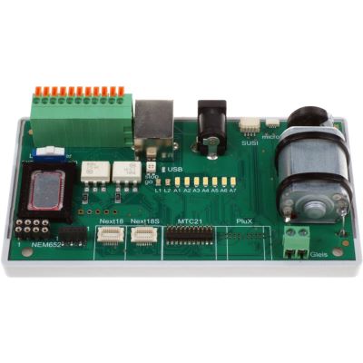
Uhlenbrock 71000 DigiTest
Testing and programming device for numerous decoder and SUSI interfaces.
View product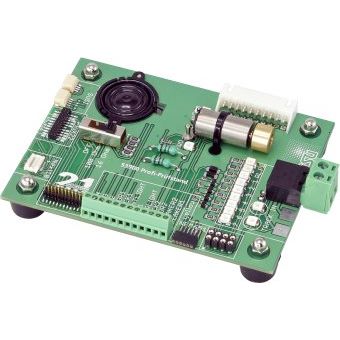
Test stand
ESU 53900 Professional Test Stand
Tests the motor, lighting, functions and sound of decoders with different interfaces.
View product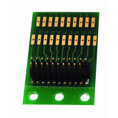

Next18 adapter
ESU 51999
Compact adapter board for small vehicles without a digital interface.
View product
N, TT, H0e and H0m gauges
Compact locomotive decoders for small vehicles
In smaller gauges, the available board area and installation height are often just as important as the interface and motor output.
Next18
ESU 59818 LokPilot 5 micro
Compact multi-protocol decoder for N, TT and small H0 vehicles.
View product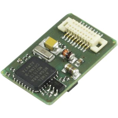
DCC Next18
Lenz 10318-01 Silver+
Small DCC decoder for digital-ready N and TT locomotives.
View product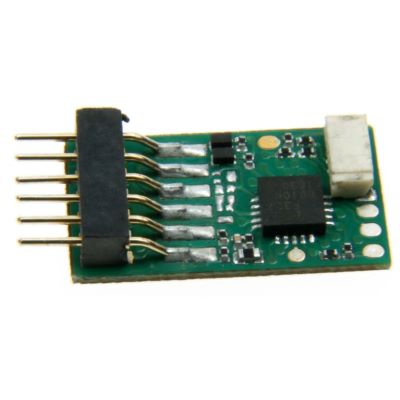
NEM 651
Uhlenbrock 73310 ID2
Miniature decoder for N and TT gauge with a six-pin connection.
View product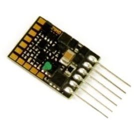
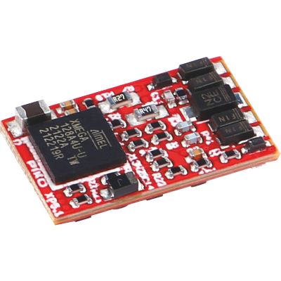
Next18
PIKO 46502 PSD XP 5.1
Multi-protocol decoder for modern vehicles with a Next18 socket.
View productH0 and selected 0 gauge vehicles
Locomotive decoders for traditional and modern interfaces
Eight-pin wired decoders, PluX22 and 21MTC versions with different function ranges are available for H0.
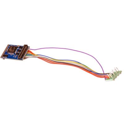
NEM 652
ESU 59610 LokPilot 5
Multi-protocol decoder for numerous traditional H0 locomotives.
View product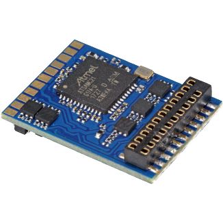
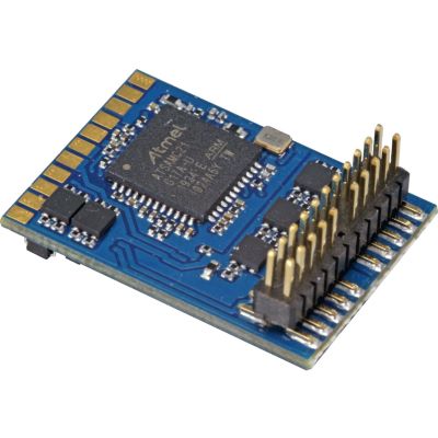
PluX22
ESU 59622 LokPilot 5 DCC
DCC decoder with numerous function options for modern H0 locomotives.
View product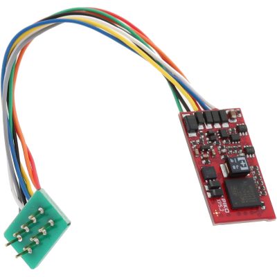
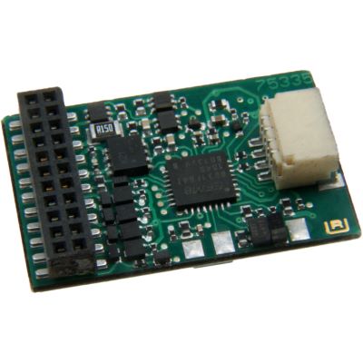
21MTC
Uhlenbrock 75335 ID2
21MTC decoder with extensive control and feedback functions.
View productSound upgrades for N, TT, H0 and 0 gauge
Sound decoders with different interfaces
In addition to the interface, the sound project, loudspeaker impedance, sound enclosure and total installation space must be compatible with the vehicle.
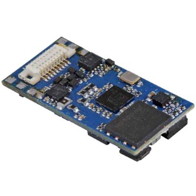
Next18 sound
ESU 58818 LokSound 5 micro
Compact sound decoder for small vehicles with a Next18 interface.
View product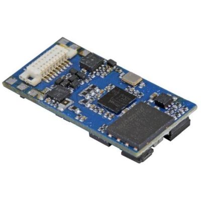
NEM 651 sound
ESU 58816 LokSound 5 micro
Six-pin sound decoder for compact digital conversions.
View product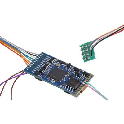
NEM 652 sound
ESU 58410 LokSound 5
Blank sound decoder for traditional H0 locomotives with an eight-pin plug.
View product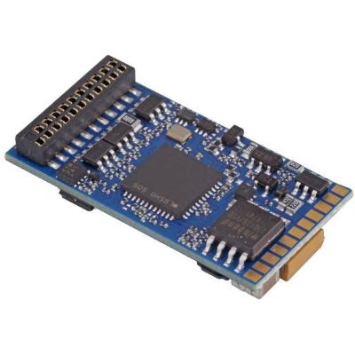
21MTC sound
ESU 58419 LokSound 5
Multi-protocol sound decoder for H0 and selected 0 gauge models.
View product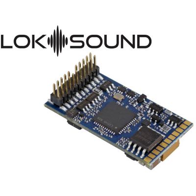
PluX22 sound
ESU 58412 LokSound 5
Blank sound decoder for modern PluX22 locomotives in H0 and 0 gauge.
View product
Answers before and after conversion
Frequently asked questions about installing model railway decoders
Where information differs, the current instructions supplied by the vehicle and decoder manufacturers take priority.
Can I install any decoder in any locomotive?
No. In addition to the interface, the motor current, decoder size, digital protocol, function outputs and, where applicable, the loudspeaker must be compatible with the vehicle.
How do I identify my locomotive's interface?
Check the packaging, operating instructions and spare-parts sheet. The number of contacts and plug design provide only an initial guide.
Does the motor have to be completely isolated?
Yes, for a hard-wired installation. Neither motor connection may be connected to a rail connection or conductive frame.
Can a decoder be inserted the wrong way round?
This is possible with NEM 651 and NEM 652. Coded interfaces must also be aligned correctly and inserted without force.
Why does the decoder become hot after installation?
Possible causes include a short circuit, a motor that has not been isolated, excessive motor current or an overloaded function output.
Why does the locomotive travel in the wrong direction?
Check the installation orientation and motor connections. Depending on the decoder, the direction can subsequently be corrected through a configuration setting.
Why should I use a programming track?
It makes it possible to read the decoder and helps identify connection errors more quickly before normal operation.
Can I reinstall the analogue blanking plug later?
Normally yes, provided it has been stored without damage and was designed specifically for the vehicle circuit board concerned.
Can sound be added during the decoder installation?
Yes, provided there is sufficient space for the decoder, loudspeaker, sound enclosure and wires and the impedance is compatible with the decoder.
How should I secure a decoder inside the vehicle?
Use a purpose-made holder or heat-resistant adhesive pad. The decoder must not be crushed or completely thermally insulated.
What should I do if the command station reports a short circuit?
Switch off immediately and check the motor isolation, plug position, solder joints, wires and any possible contact with the metal frame.
Can a decoder also be installed in a G gauge vehicle?
In principle, yes. Large-scale motors and auxiliary functions require more powerful decoders with appropriately high current capacities.
The most important installation rule
Measure and check first, then connect the decoder
A successful conversion does not begin with a soldering iron. It begins by clearly identifying the vehicle, interface, motor and installation space. A decoder that fits mechanically may still be electrically unsuitable.
With digital-ready vehicles, installation is normally limited to removing the blanking plug and carefully inserting the correct decoder. With older locomotives, adapter boards are often clearer and easier to maintain than loose wiring.
Further basic information is available in Digital Model Railways: The Basics Explained , Locomotive Decoders and Digital Modules Explained and the Decoder Finder .
More information about decoders and digital model railways
Discover further guides about interfaces, sound, digital protocols, locomotive conversions, gauges, vehicle technology and layout planning.