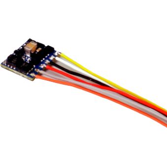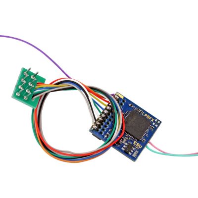




Shape
Two Rows of Four Openings
The socket is rectangular and has eight contacts. An analogue blanking plug is often fitted initially.

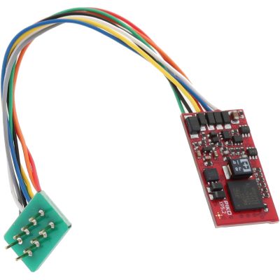
The eight-pin NEM 652 interface is widely used in many H0 locomotives. It connects the track, motor and driving lights to the decoder. This guide explains the correct pin assignment and helps you choose locomotive, function and sound decoders.
The term 8-pin describes a standardised electrical interface between the vehicle circuit board and decoder. The socket is located inside the vehicle. The decoder has a connector with two rows of four contacts.
These eight contacts carry the two track connections, two motor connections, front light, rear light and common positive connection for the lighting. Contact 3 is unused in the basic assignment but may be used by the vehicle manufacturer for an auxiliary function.
NEM 652 is found mainly in older and more simply equipped H0 locomotives. Some N-, TT- and Gauge 0 vehicles may also have an eight-pin socket, so gauge alone is not a reliable indicator.
An eight-pin connector also says nothing about the digital protocol. The decoder may support DCC, Motorola, multiple protocols or additional mfx-compatible features. Motor current, decoder dimensions and digital format must be checked independently of the interface.
The socket is rectangular and has eight contacts. An analogue blanking plug is often fitted initially.
A dot, arrow, number or coloured wire often indicates the position of the first contact.
On a standards-compliant decoder, the orange motor wire leads to contact 1.
The blanking plug connects the motor and lighting for analogue operation. It is replaced by the decoder.
The socket may be located directly beneath the body. The wires, decoder height and bending radius also require space.
Depending on its production year, the same locomotive model may have NEM 652, PluX, 21MTC or no interface.
The illustration shows the usual view of the vehicle socket. Any vehicle-specific use of contact 3 must be documented in the instructions.
Many eight-pin connectors are not fully polarised. If the decoder is inserted after being rotated by 180 degrees, the motor and track connections may still remain fundamentally connected, but the lighting and common return can be assigned incorrectly.
Therefore, check the marking on the vehicle circuit board, the orange wire on the decoder connector and the manufacturer instructions together. When the orientation is unclear, do not test the decoder experimentally at full track voltage.
| Contact | Function | Wire Colour | Connection | Note |
|---|---|---|---|---|
| 1 | Motor Connection 1 | Orange | Decoder to motor | Often used to identify pin 1 |
| 2 | Rear Lighting | Yellow | Rear headlight or tail light | Output normally switches to negative |
| 3 | Unused or Auxiliary Function | Green | Manufacturer-specific | Assignment must be documented |
| 4 | Left-Hand Track Pickup | Black | Left rail or vehicle side | Do not confuse it with a motor wire |
| 5 | Motor Connection 2 | Grey | Decoder to motor | Motor must be isolated from the rails |
| 6 | Front Lighting | White | Front headlight | Direction-dependent programming possible |
| 7 | Common Lighting Connection | Blue | Common positive | Do not connect directly to a rail |
| 8 | Right-Hand Track Pickup | Red | Right rail or vehicle side | Supplies the decoder with the track signal |
| Interface | Contacts | Typical Gauge | Strengths | Limitation |
|---|---|---|---|---|
| NEM 652 | 8 | Mainly H0 | Simple, widespread and easy to retrofit | Only a few functions through the connector |
| NEM 651 | 6 | N, TT and small H0 | Very compact | No common positive in the basic connection |
| Next18 | 18 | N, TT and small H0 | Compact with additional functions | Different socket and not interchangeable |
| PluX22 | 22 positions | Mainly H0 | Numerous lighting and sound connections | Pins are located on the decoder |
| 21MTC | 21 contacts | H0 and some Gauge 0 models | Numerous auxiliary functions | Pins are located on the vehicle circuit board |
NEM 652 is rare because of its size. An eight-pin cable connector can nevertheless be found in some older or larger N-gauge vehicles.
NEM 651, Next18 or a compact wired version.
Some TT vehicles have NEM 652. NEM 651, Next18 and PluX12 are more common, however.
The space above the socket and the length of the wiring harness.
The eight-pin interface is particularly widespread here. Many models from earlier digital generations can be retrofitted easily.
LokPilot, SmartDecoder, Standard+ or a sound decoder.
NEM 652 may be found in larger narrow-gauge vehicles, although installation space is often limited.
Decoder height, flywheel and body supports.
Some smaller Gauge 0 vehicles may have an eight-pin socket. However, the motor current can exceed the rating of typical H0 decoders.
Continuous current and starting current under load.
NEM 652 is generally not the preferred solution for large vehicles. Free wiring, screw terminals and large-scale interfaces provide a greater power reserve.
L, XL or garden-railway decoders.
The motor, gearbox, current pickup and lighting must operate without faults.
Release screws and clips according to the instructions without tearing off any wires.
Photograph the position of pin 1, the blanking plug and the cable connections.
Pull it out straight and retain it for possible future analogue operation.
Align pin 1, do not tilt the connector and route the wires safely.
Read the address and initially test the motor and lighting at low speed.
Check pin 1 and the orange wire before inserting the decoder.
Eight contacts do not automatically mean that the dimensions, motor current and protocol are suitable.
Older H0 drives can draw a high current, particularly when starting.
A vehicle-specific auxiliary assignment must be documented and protected.
The common positive lighting connection must not be connected directly to a track connection.
The decoder, loudspeaker and sound enclosure require significantly more space together.
The product selection covers different digital formats, output levels and applications. Before ordering, compare decoder dimensions, motor current and required functions with the vehicle.
For motor control, driving lights and basic auxiliary functions in H0 locomotives.
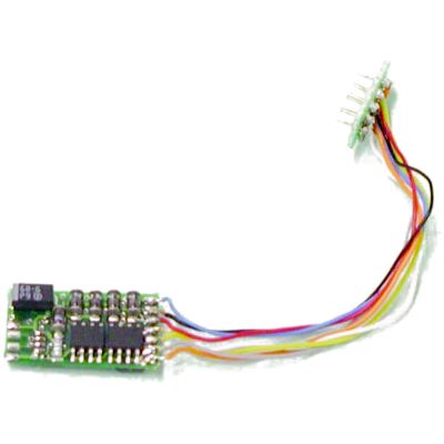
Proven decoder for DCC and Motorola.
View Product →
Auto-adaptive motor control and extensive function mapping.
View Product →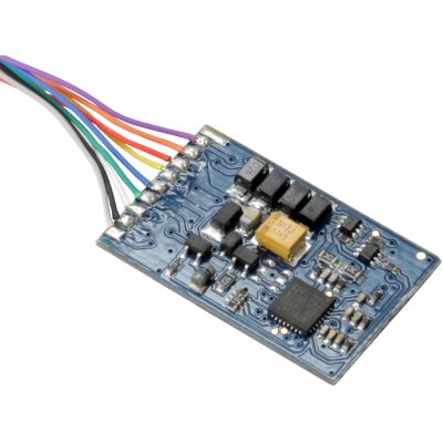
DCC decoder with RailComPlus and Autotune.
View Product →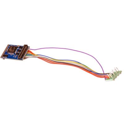
For DCC, Motorola, Selectrix and M4.
View Product →
DCC-only version with modern motor control.
View Product →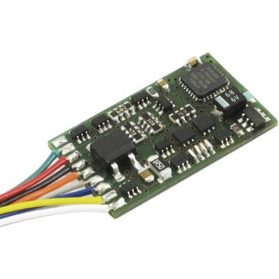
Straightforward decoder with ABC and RailCom.
View Product →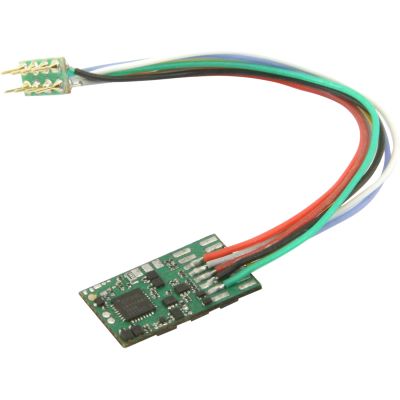
Compact decoder with extended function mapping.
View Product →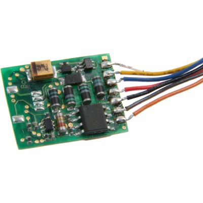
Modern decoder for flexible H0 conversions.
View Product →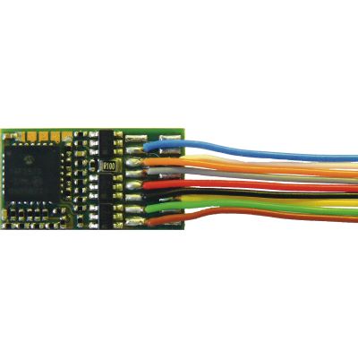
Feedback-capable decoder for offset installation.
View Product →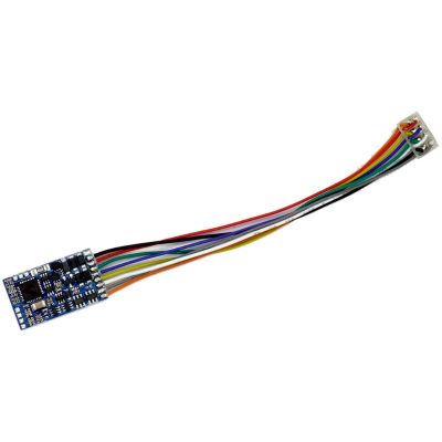
Load-controlled eight-pin version for H0.
View Product →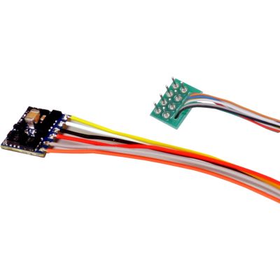
Compact version for restricted installation space.
View Product →For control cars, interior lighting and vehicles without a regulated traction motor.
Universal blank decoders and prepared sound solutions with an eight-pin cable connector.
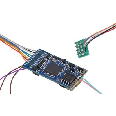
Universal sound decoder for custom projects.
View Product →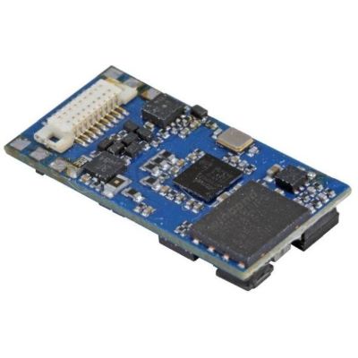
Compact multiprotocol sound decoder with an eight-pin connector.
View Product →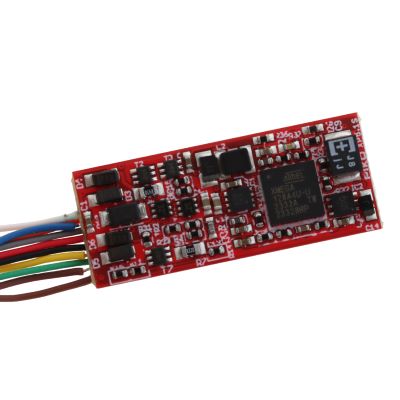
Blank sound version without a loudspeaker.
View Product →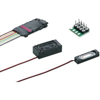
Prepared retrofit solution for diesel locomotives.
View Product →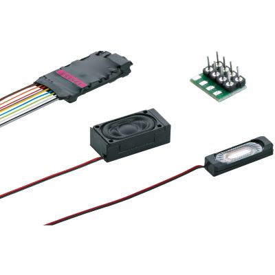
Sound decoder with a preloaded electric-locomotive sound.
View Product →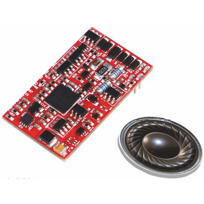
Model-specific sound decoder with a loudspeaker.
View Product →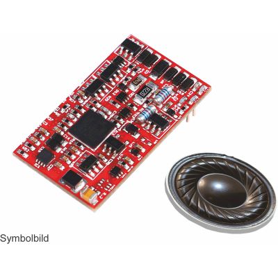
Sound solution for suitable Taurus models.
View Product →NEM 652 is an eight-pin electrical interface for model railway vehicles. The socket has two rows of four contacts.
No. In addition to the connector, the decoder dimensions, motor current, digital protocol and range of functions must suit the locomotive.
Pin 1 is often marked by a dot, arrow, number or the orange motor wire on the decoder connector.
The motor and lighting may respond incorrectly. Disconnect the power immediately, remove the decoder and align it correctly.
This is possible when the locomotive has a suitable NEM 652 socket and compatible DC motor and the command station can transmit DCC.
Yes. The protocol is independent of the interface. The decoder only needs to fit mechanically and electrically.
Contact 3 may remain unused or be employed by the vehicle manufacturer for an auxiliary function. Its assignment must be documented.
Yes, provided that sufficient space is available for the decoder, loudspeaker, sound enclosure and wiring.
No. 21MTC has considerably more contacts and uses a different connector principle.
A conversion is possible with a suitable adapter or replacement circuit board, but it must match the locomotive wiring and available installation space.
The permitted continuous-current rating of the specific decoder is decisive. Measure the actual motor current under load.
Professional installation is advisable when the circuit-board pin assignment is unknown, the motor is old, the vehicle is valuable or an extensive sound conversion is planned.
The pin assignment, wire colours and basic mechanical dimensions of the NEM 652 recommendation were considered.
Content status: 17 July 2026. Check the current vehicle and decoder instructions before installation.
The main guide covers locomotive decoders, sound decoders, digital command stations, interfaces, digitisation and layout planning.