Check the track voltage
Test another known working locomotive and check the STOP state, booster and connection box.

Is the locomotive stationary, are the lights and sound not working or is the command station unable to read the decoder? This guide covers the power supply, address and digital protocol before moving on to the interface, motor, programming lock and possible decoder damage.
A decoder that does not respond is not necessarily defective. The locomotive may not be receiving reliable track power, it may be addressed using a different number or the command station may be transmitting an incompatible digital protocol. An incorrectly activated long DCC address or an active consist address may also make the decoder appear to have failed completely.
When the lighting or sound works but the motor does not, the cause is more likely to involve the motor wiring, mechanism, overload protection or motor control. When the complete vehicle remains inactive, diagnosis should begin with the track, command station, interface and decoder power supply.
If the decoder was programmed shortly before the fault occurred, check the address, CV 29, function mapping and any programming locks. A factory reset should be considered only after identifying the decoder precisely and confirming the manufacturer-specific reset procedure.
Switch off the track voltage immediately and allow the vehicle to cool. A damaged or severely overheated decoder must not be powered repeatedly or investigated further on the programming track.
These steps do not change decoder values and rule out the most common external causes.
Test another known working locomotive and check the STOP state, booster and connection box.
Place the locomotive on a clean, straight track and check current pickup from both rails.
When the DCC address is unknown, first test the commonly used factory address.
Electrically isolate the programming track and remove every other vehicle.
Check the power supply, interface, decoder plug and possible short circuits first. The address and mapping come afterwards.
The decoder is receiving power and commands. The motor connections, motor current, mechanism and logical driving permissions become more likely causes.
A short, long or consist address remains active. Correct the locomotive record and decoder values together.
Programming locks, reset values and automatic registration differ between manufacturers. Use the instructions for the decoder family actually installed.








| Area to check | Typical fault | Safe test |
|---|---|---|
| Short DCC address | CV 1 contains another address | Read CV 1 on the programming track or test address 3 |
| Long DCC address | CV 17 and CV 18 are active, but the locomotive record uses CV 1 | Use CV 29 and the command station's address assistant |
| Consist address | CV 19 still contains a multiple-unit or consist address | Check the consist address and disable it when necessary |
| DCC / Motorola | The command station and locomotive record use different formats | Check the protocol selected in the vehicle record |
| mfx / M4 | The locomotive was deleted or registration was not completed | Place only this locomotive on the track and wait for automatic registration |
| Decoder lock | CV 15/16 or a manufacturer-specific lock prevents changes | Check the instructions and unlock the decoder deliberately |
| ZIMO programming lock | CV 144 blocks certain programming operations | Unlock it only as described in the ZIMO instructions |
The assistant identifies the first area to inspect. It does not write CVs or trigger a reset. Begin with the simplest external cause and change only one setting at a time.
A decoder that cannot be read is not necessarily defective. Contact problems, buffer storage, unsuitable programming-track conditions or an active programming lock may prevent acknowledgement.
If a newly installed decoder has never worked, check the interface pin assignment, motor isolation and wiring before writing an address or reset value.
Select the symptom and digital system.
Test another locomotive on the same track, clean the wheels and check the decoder plug and possible short circuits.
Use a known working locomotive on the same section of track. Check the STOP button, booster and connection box.
Clean the wheels, pickup shoe, wheel contacts and programming track. Reposition the locomotive slightly several times.
Determine the manufacturer, family, interface and correct instructions. The locomotive brand does not necessarily identify the decoder manufacturer.
Check the DCC address, long addressing, consist address, Motorola vehicle record and mfx registration.
Check NEM 652, Next18, PluX or 21MTC connections with the power switched off. Never force a plug into its socket.
When the lighting works, check the motor connections, motor isolation, gearbox and possible overload.
Exclude the lighting, sound, coupler, smoke generator and buffer storage individually as possible causes.
Check CV 15/16 or manufacturer-specific locks only as described in the instructions and unlock them deliberately.
Save the project first. Use only the reset command specified for the exact decoder family.
Do not continue operating a decoder that smells, becomes hot, is visibly damaged or still does not respond after the vehicle has been checked.
| Gauge | Typical difficulty | First check |
|---|---|---|
| Z / N | Very small contacts and decoders | Check the wheels, contact springs, installation position and temperature |
| TT | PluX12, Next18 and older motors | Identify the interface and actual decoder manufacturer |
| H0 | DCC, mfx, Motorola and numerous interfaces | Compare the locomotive record, protocol and circuit-board pin assignment |
| H0e / H0m | Short current-pickup base | Do not confuse contact problems with a need to reset the decoder |
| 0 / 1 / G | High motor and function currents | Check the power reserve, booster, wiring and large-scale decoder |
The command station and decoder may use different speed-step settings. Check 14, 28 and 128 speed steps.
Check the digital address, data format and locomotive record. Analogue operation does not prove that the digital configuration is correct.
Check the function mapping, available function-button range and physical outputs.
Place only the affected locomotive on the track, leave the command station switched on and repeat the registration process.
Check the programming lock, programming mode and decoder family. Not every CV exists in every decoder.
Check the factory address, protocol and renewed mfx registration. A reset may overwrite individual settings.
Select a replacement decoder only after inspecting the motor, wiring and vehicle circuit board. Compare the interface, digital protocol, motor current, function outputs and installation dimensions.
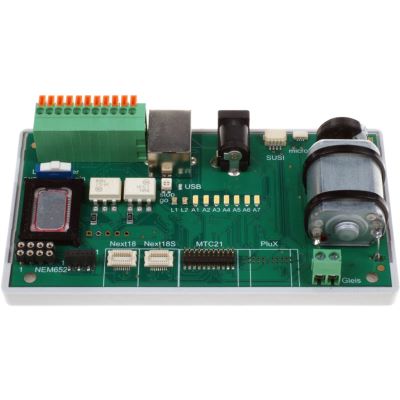
Test decoders outside the locomotive using several interfaces.
View product
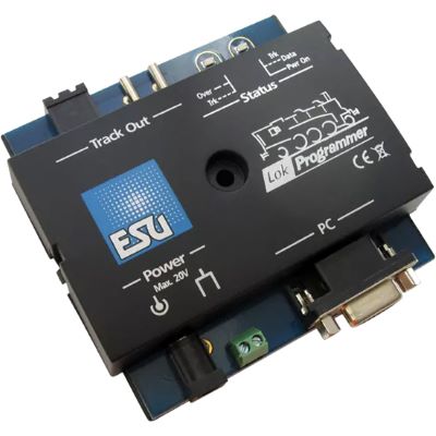
Save ESU projects, identify decoders and inspect their settings.
View product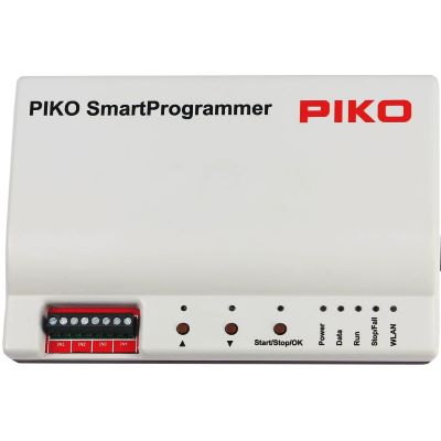
Edit SmartDecoder projects, diagnostic data and functions.
View product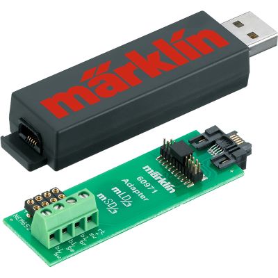
Configure retrofit decoders on a computer and transfer projects.
View product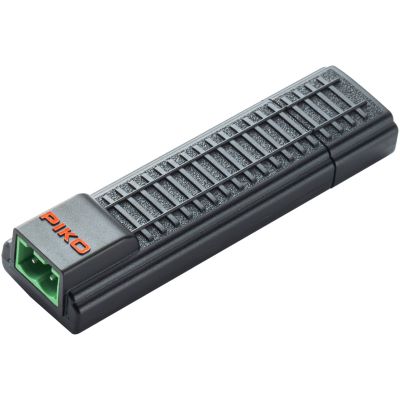
Compact programming interface for compatible SmartDecoder XP projects.
View product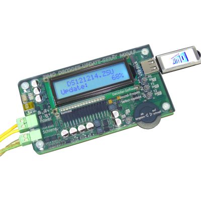
Program and update ZIMO decoders and manage decoder projects.
View product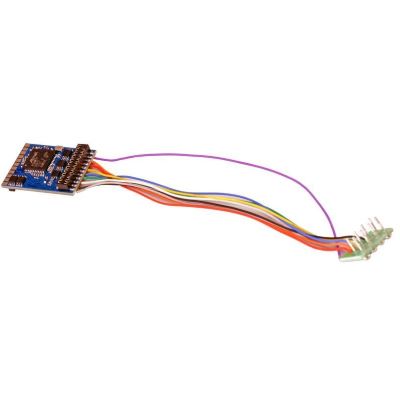
Multi-protocol decoder with an eight-pin connection.
View product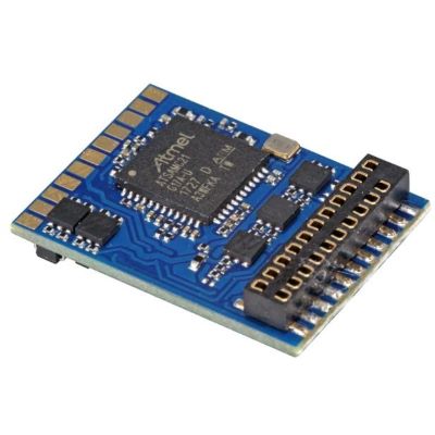
DCC decoder for vehicles with a 21MTC interface.
View product
PluX22 locomotive decoder for extensive H0 functions.
View product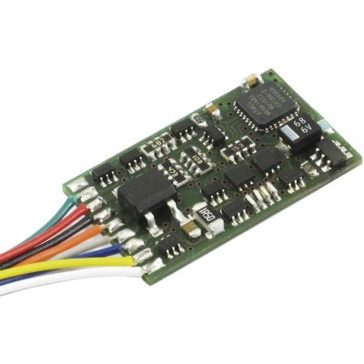
DCC locomotive decoder with a conventional NEM 652 plug.
View product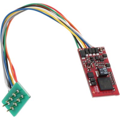
Multi-protocol decoder with an eight-pin interface.
View product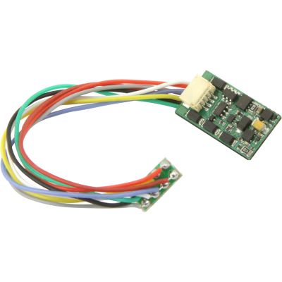
Locomotive decoder for NEM 652 and several digital formats.
View product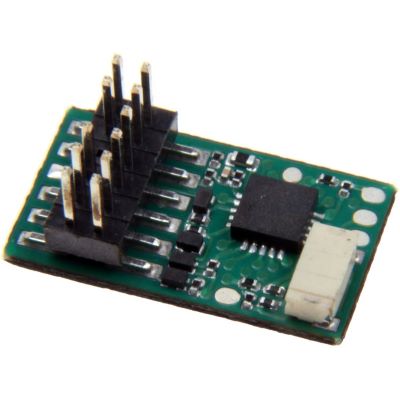
PluX12 decoder for appropriately prepared TT vehicles.
View product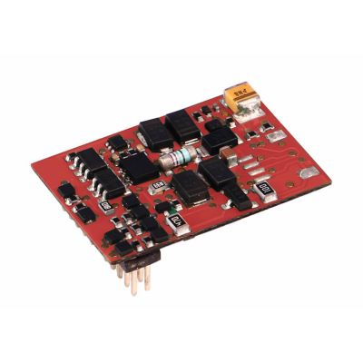
Compact multi-protocol decoder for TT gauge.
View product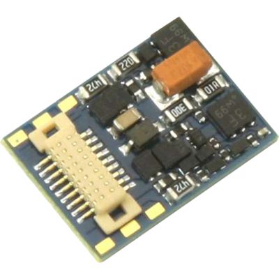
Multi-protocol micro decoder with a Next18 interface.
View product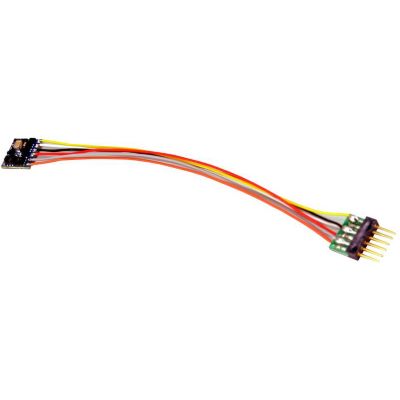
Micro decoder with a six-pin NEM 651 connection.
View product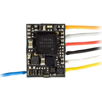
Very compact decoder for small vehicles.
View product
Compact wired decoder for small locomotives.
View product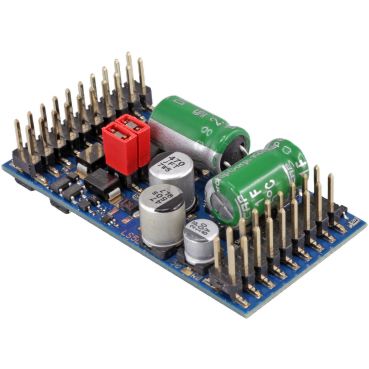
High-output decoder for larger motors and several protocols.
View product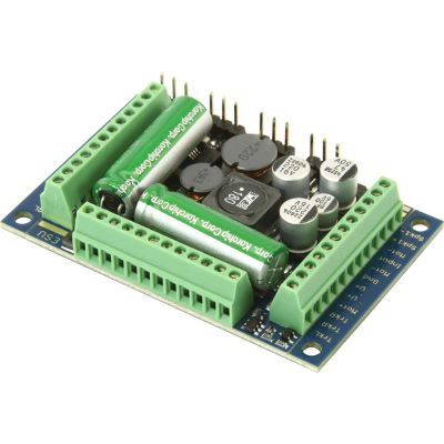
XL sound decoder for high motor currents and auxiliary functions.
View product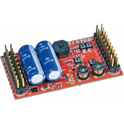
Blank large-scale sound decoder for custom projects.
View product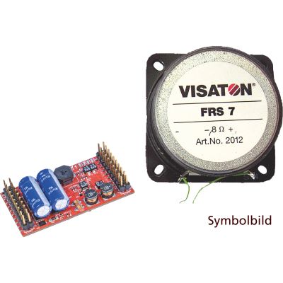
Vehicle-specific large-scale sound decoder.
View productMany new or reset DCC decoders use address 3. Factory-fitted digital vehicles may use another initial address.
A long address in CV 17 and CV 18 or a consist address in CV 19 is probably active.
Contact problems, programming locks, buffer storage or unsuitable programming conditions may prevent acknowledgement.
Check the motor wiring, motor isolation, mechanism, overload protection and motor-control settings.
Place the locomotive by itself on the programming track and read CV 1 and CV 29. When long addressing is active, also check CV 17 and CV 18.
Place only the affected locomotive on the track, check old or incorrect vehicle records and wait for automatic registration to finish completely.
Yes. Depending on the manufacturer, CV 15/16 or other CVs may block changes. The driving function itself is not necessarily disabled.
No. Check the power supply, address, protocol, interface and wiring first. A reset overwrites individual settings.
Yes. Check the plug and interface with the power switched off. Mechanically keyed interfaces must never be forced together.
A decoder must not be reused when there is a smell, discolouration, severe heat, visible damage or no response after testing it in a confirmed fault-free vehicle or testing board.
Further instructions, decoder guides and buying advice are available in the central model railway guide.