Mild and stable warming
The vehicle runs smoothly, every function works and the temperature does not continue rising during a longer run. Nevertheless, check the installation and ratings after a new conversion.

If a locomotive decoder becomes very warm quickly, repeatedly switches off or produces an unusual smell, switch off the track voltage immediately. This guide explains how to check the motor current, wiring, function outputs, track voltage, loudspeaker, buffer storage and installation conditions systematically.
An operating decoder converts part of the electrical energy it consumes into heat. Mild, stable warming can therefore occur during normal operation. The motor output stage, voltage regulator, sound amplifier and several simultaneously active function outputs all generate power losses.
The situation becomes critical when the temperature rises noticeably within a short time, the vehicle runs jerkily or switches off, lighting outputs flash, an electronic or hot-plastic smell develops or components become discoloured. The locomotive must then no longer be operated. A protection cut-off is a warning, not an invitation to repeat the test run.
Common causes include excessive or stalled motor current, a partial short circuit to the chassis, trapped wires, overloaded lighting outputs, an unsuitable loudspeaker impedance, an incorrectly wired energy-storage circuit, excessive track voltage or a decoder whose current rating is insufficient for the vehicle.
Remove the locomotive from the track after it has cooled completely. Do not switch it on again until the wiring, motor, connected loads and decoder have been inspected. A visibly damaged decoder must not be placed on the programming track.
The vehicle runs smoothly, every function works and the temperature does not continue rising during a longer run. Nevertheless, check the installation and ratings after a new conversion.
The temperature rises, the locomotive runs jerkily, the lights flicker or individual functions fail. End operation and identify the cause systematically before another test run.
Switch off the track voltage immediately. Do not touch the decoder while it is hot and do not operate the vehicle again. Professional inspection or replacement is required.
Leave the vehicle in the condition in which the fault occurred. A premature reset or several changed CV values will make diagnosis more difficult.
Press the STOP button and remove the vehicle only after it has cooled.
Repeated power cycles may permanently destroy an already damaged output stage.
Document the speed step, active functions, train load, track section and operating duration.
Check wires, plugs, circuit boards, the motor and decoder for trapped cables or discolouration.
Current limits, error memories and protection functions are manufacturer-specific. Use only the documentation for the decoder family actually installed in the vehicle.






A binding gearbox, blocked cardan shaft, damaged motor or excessive train load may overload the motor output stage continuously.
The motor connections must not be connected to the wheel pickups, centre rail or vehicle chassis. Even occasional contact is critical.
Wires can be damaged or pressed against metal components when the body is refitted. The fault may therefore appear only after reassembly.
Too many lamps, unsuitable resistors or continuously energised digital couplers can increase power loss or trigger protection.
A voltage that is unnecessarily high for the gauge increases power loss. The command station, power supply and booster must be assessed together.
An unsupported loudspeaker or a short circuit in its wiring may overload the audio output stage of a sound decoder.
Reversed polarity, missing charging-current limitation or unsuitable solder pads can heat the decoder, rectifier or voltage regulator.
Incorrect PWM or control parameters can increase motor noise, current peaks and heat. Restore the original values first.
A micro decoder is not automatically suitable for every H0 motor. Continuous current, peak current, cooling and installation position must match the vehicle.
| When does the decoder become warm? | Likely area | First safe check |
|---|---|---|
| While stationary | Wiring, lighting, sound or voltage regulator | Switch off every function and compare the current consumption without moving the motor |
| Immediately when starting | Motor connection, blockage or motor current | Check the gearbox for free movement and confirm that the motor is electrically isolated |
| Only with a train attached | Continuous current, mechanism or excessive train load | Test the locomotive without coaches and then with a small load |
| Only with lighting or a coupler | Function output and connected load | Check the current requirement and activation-time limit of the affected AUX output |
| Only with sound | Loudspeaker, audio output or total load | Reduce the volume and check the loudspeaker specifications |
| After installing buffer storage | Polarity, charging circuit or incorrect pads | Disconnect the storage module and compare the installation with the wiring diagram |
The diagnostic assistant identifies the first sensible area to inspect. It does not change decoder values and does not replace measuring the current. A decoder that smells, is discoloured or shows visible damage must not be powered again.
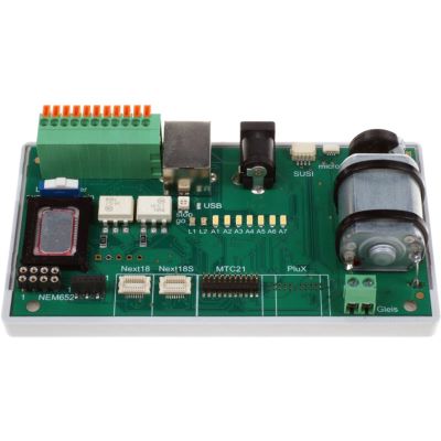
Carry out further tests on a suitable decoder testing board or a protected programming track whenever possible. Never place a loose decoder directly on a metal chassis. After refitting the body, ensure that no wires are trapped.
Some PIKO SmartDecoder XP versions can record motor, function-output and temperature faults in an error memory. With other manufacturers, protection may be indicated by flashing outputs or a temporary loss of functions.
Select when the fault occurs and which function is active.
Switch off every function and check whether the decoder continues to warm up. Inspect the motor connections, vehicle circuit board and possible connections to the chassis.
Remove the locomotive from the track and allow any energy-storage module to discharge as specified by the manufacturer. Do not touch hot components.
Record the manufacturer, catalogue number, interface and permitted motor and output currents.
Check the circuit board, wires, plugs, heat-shrink tubing and chassis for discolouration, trapped wires and solder bridges.
There must be no unintended conductive connection between the motor terminals and the track connections or chassis.
Inspect the gears, bearings, cardan shafts and wheels for binding. Do not test a blocked motor digitally.
Remove newly installed lighting, couplers, smoke generators, loudspeakers or buffer storage from the test circuit one at a time.
Set a voltage suitable for the gauge and decoder approval. A more powerful booster does not solve a vehicle fault.
Only test an undamaged decoder. Use a low speed step, no train load and no unnecessary functions.
End the test immediately if the load rises sharply or the decoder switches off again.
If the decoder continues to overheat in a fault-free vehicle, have it inspected or replace it with a suitably rated model.
| Gauge | Typical challenge | Check particularly carefully |
|---|---|---|
| Z gauge | Very small decoders with limited cooling area | Component height, motor current, contact quality and clearance from the body |
| N gauge | Confined installation space and compact motors | Do not trap a micro decoder between the motor and a metal weight |
| TT gauge | Older motors inside relatively small bodies | Measure the continuous current and inspect the mechanism before selecting a decoder |
| H0 gauge | Many different motor and interface generations | Motor type, vehicle circuit board, AUX load and interface variant |
| H0e / H0m | Small vehicles despite the H0 scale | Plan the micro decoder, wire routing and heat dissipation carefully |
| Gauge 0 | Higher motor current and numerous auxiliary functions | Use a high-output decoder, suitable wire sizes and the combined current requirement |
| Gauges 1 / G | High currents, smoke, sound and outdoor operation | Large-scale decoder, track voltage, cooling and multi-motor operation |
An overloaded output may switch off and retry repeatedly. Check the load, inrush current and wiring.
The motor output stage may be switching off because of excess current or temperature. Check the mechanism and motor current before further tests.
The affected AUX output may be overloaded or damaged. Disconnect the load and never attempt to force a higher output current.
The problem is probably not limited to CV settings. The wiring, motor, connected loads or decoder hardware must be inspected.
The decoder may be trapped, touching metal or unable to dissipate heat. Replan the wire routing and installation position.
A binding or faulty motor is likely. End operation and inspect the drive independently of the digital decoder.
Select a replacement decoder only after the cause of the overheating has been identified. Compare the interface, continuous current, peak current, number of connected loads, installation space and motor type.
Test decoders outside the vehicle using several interface connections.
View product
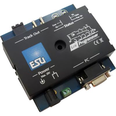
Save decoder projects and inspect motor, output and sound settings.
View product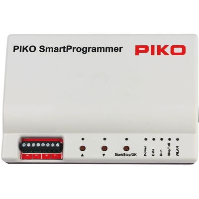
Inspect SmartDecoder projects, error memories and configuration settings.
View product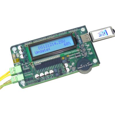
Decoder programming, firmware maintenance and project management.
View product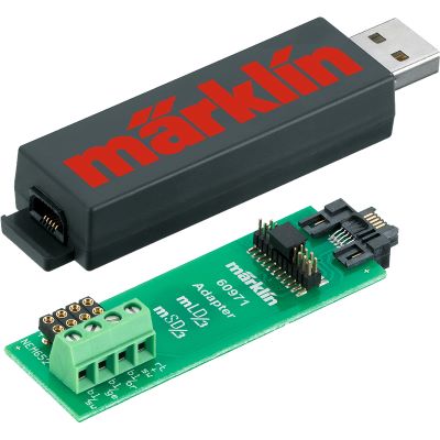
Configure retrofit decoders and save existing decoder projects.
View product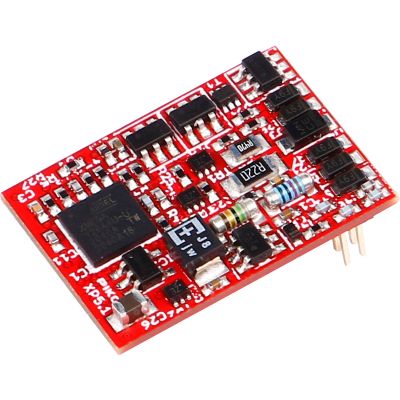
PluX22 multi-protocol decoder for modern H0 vehicles.
View product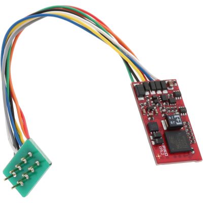
Eight-pin multi-protocol decoder for conventional H0 interfaces.
View product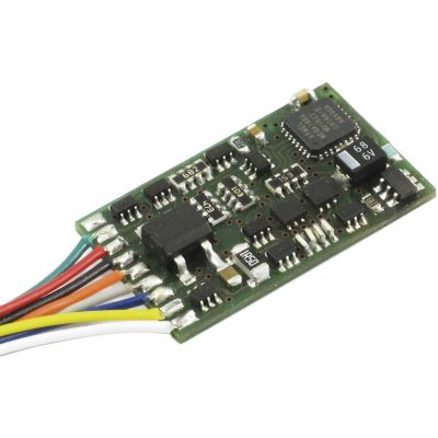
DCC locomotive decoder for vehicles with an NEM 652 interface.
View product
PluX22 decoder for vehicles with extensive functions.
View product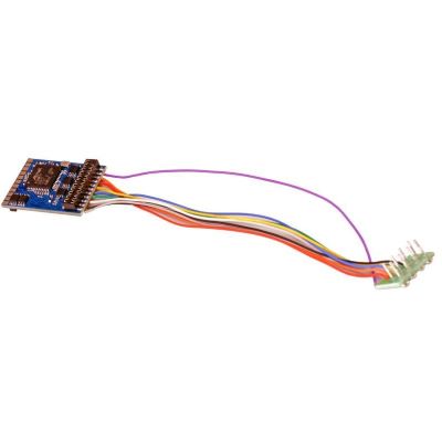
Multi-protocol decoder with an eight-pin NEM 652 connection.
View product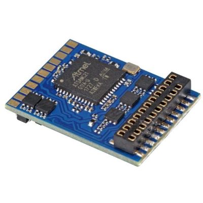
DCC locomotive decoder for vehicles with a 21MTC interface.
View product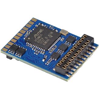
Multi-protocol decoder for modern 21MTC vehicle circuit boards.
View product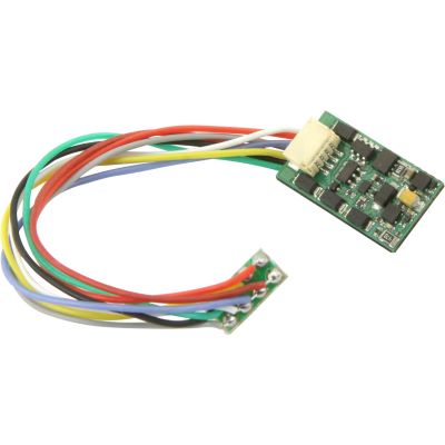
NEM 652 locomotive decoder for DCC, Motorola and mfx-oriented layouts.
View product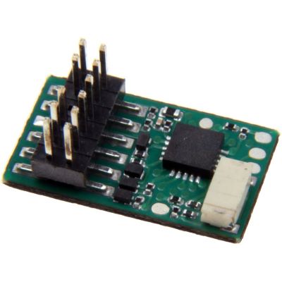
PluX12 decoder for appropriately prepared TT vehicles.
View product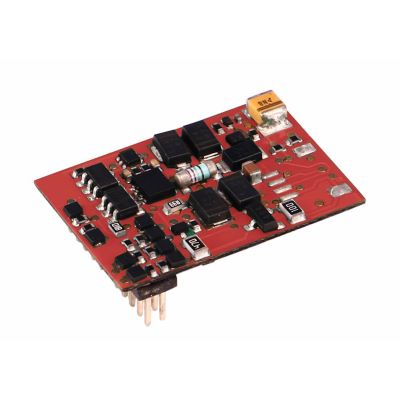
Compact multi-protocol decoder for TT gauge.
View product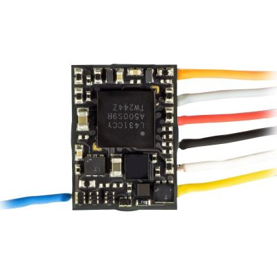
Very compact decoder for small motors and restricted installation space.
View product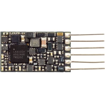
Low-profile NEM 651 decoder for compact N and TT vehicles.
View product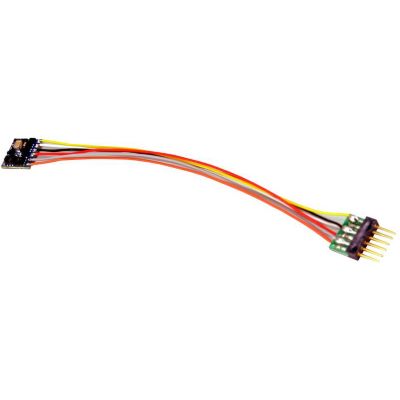
Micro decoder with a six-pin NEM 651 connection.
View product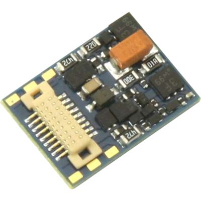
Multi-protocol micro decoder for modern compact vehicles.
View product
Compact wired decoder for small locomotives and narrow gauge.
View product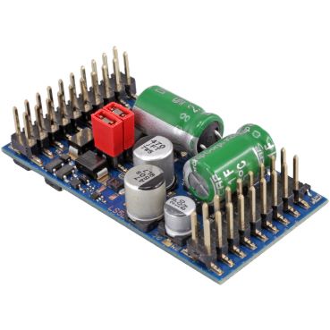
High-output decoder for larger motors and extensive functions.
View product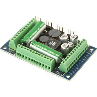
XL sound decoder for powerful motors and auxiliary functions.
View product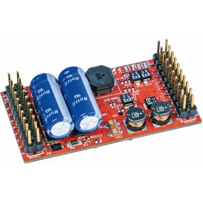
Large-scale sound decoder for custom PIKO sound projects.
View product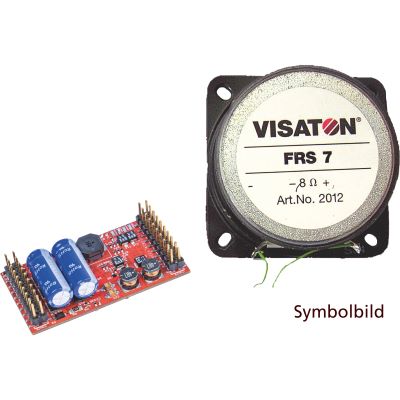
Vehicle-specific garden-railway sound decoder with loudspeaker.
View productMild, stable warming can be normal. Increasing heat, interruptions, smell, discolouration or a protection cut-off are warning signs.
Switch off the track voltage immediately, allow the vehicle to cool and do not power it again until the motor, wiring and connected loads have been inspected.
Yes. Blocked gears, dry bearings, defective windings or a binding drive increase the motor current and load the decoder output stage.
Unsuitable motor-control or PWM settings and continuously active high-current functions may increase the load. A reset will not correct a genuine short circuit.
The function outputs may be overloaded. Check the lamp current, LED resistors, common return and maximum permitted output load.
Yes. An unsuitable impedance, damaged wiring or a loudspeaker short circuit may overload the audio output stage.
The decoder may be trapped, touching metal or affected by compressed wires. Heat dissipation may also be considerably poorer.
No. The motor current, peak load, cooling, installation space and number of connected loads must match the decoder.
No. A booster with a higher output current does not correct a vehicle fault and may increase damage when the protection settings are unsuitable.
Yes. Reversed polarity, an unsuitable charging circuit or incorrect solder pads can overload both the decoder and storage module.
Only when there is no visible damage and the cause has been confirmed as an incorrect setting. Inspect the wiring, motor and connected loads first.
A decoder must no longer be used when there is a smell, discolouration, damaged components, repeated overheating or heat generation in a confirmed fault-free vehicle.
Further decoder guides, diagnostic instructions and buying advice are available in the central model railway guide.