Modellbahn Keks
Welcome!
Our cookies offer you a fast, relaxed and full-featured shopping experience. Some are necessary to operate the website and its functions. Others help us to improve our services. If you agree to this, simply consent to the use of cookies for preferences, statistics and marketing by clicking on "OK". Alternatively, you can deactivate individual cookies under "Customise cookies" or all cookies, except those required for the function of our website, under "Reject all".
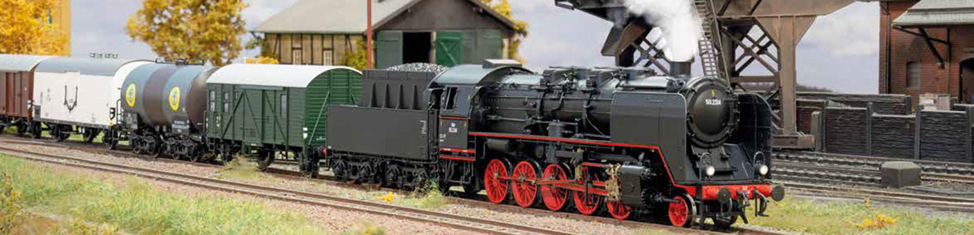
Digital model railway with a locomotive, track and electronic control system
Understanding the differences between digital components

Locomotive Decoders & Digital Modules Explained | Modellbahnshop

What is a locomotive decoder, function decoder, accessory decoder, feedback module, booster or digital bus? This guide explains the tasks, differences, applications and selection criteria of the most important digital components for H0, TT, N, Z, 0, 1 and G.

Six components with different tasks

Which Digital Module Does What?

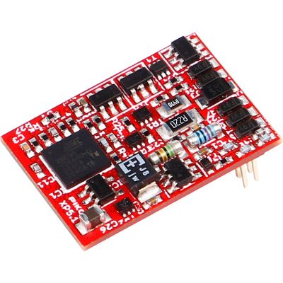
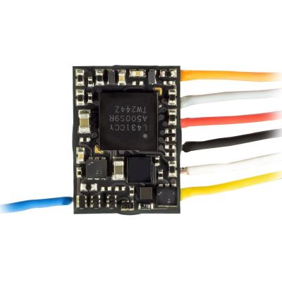
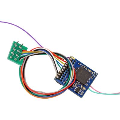
A locomotive decoder is installed in a locomotive or railcar. It controls the motor and additional vehicle functions. A function decoder, by contrast, does not have a regulated motor output. It is intended for lighting, couplers and other electrical functions in coaches or functional models.

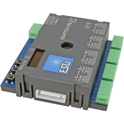
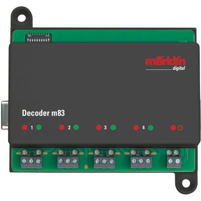
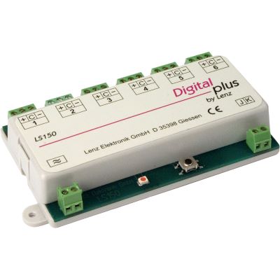
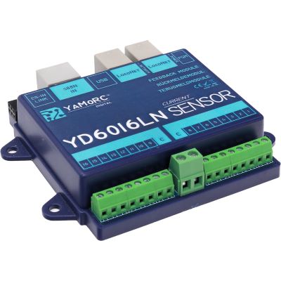
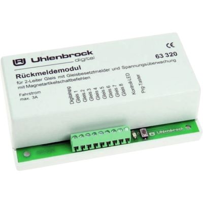
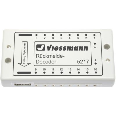
An accessory decoder is normally installed in a fixed position beneath or beside the layout. It switches turnouts, signals, relays, lighting or uncouplers. A feedback module works in the opposite direction: it detects a state and reports it to the command station or control software.

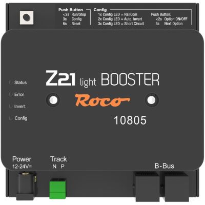
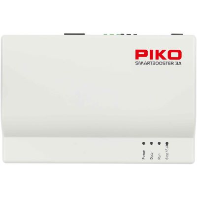
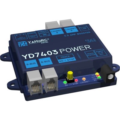
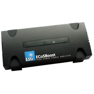
A booster provides additional electrical power for a track district. A digital bus connects the command station with handheld controllers, feedback modules, accessory modules, boosters and other system devices.

These components therefore perform completely different tasks. They can be used together on the same layout, but they are not interchangeable.

Component Installation Location Main Task Typical Application
Locomotive decoder Locomotive or railcar Control the motor and vehicle functions Driving, lighting, couplers and smoke
Function decoder Coach or functional model Switch outputs without motor control Interior and tail lighting
Accessory decoder Beneath or beside the layout Operate stationary electrical loads Turnouts, signals and relays
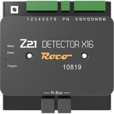
Feedback module At track sections or contacts Report states to the control system Block operation and staging yards
Booster Between the command station and track district Supply the digital signal with power Additional power districts
Digital bus Between system devices Transmit data and sometimes power Connect controllers, detectors and modules
The digital components in detail

Decoders, Feedback, Power and Data Connections Explained

The following answers explain the definition, installation location, selection criteria and a practical example for each component.

What Is a Locomotive Decoder?

A locomotive decoder is an electronic receiver installed in a locomotive or railcar. It receives digital commands through the track, recognises its own address and controls the connected motor. It also switches lighting, digital couplers, smoke generators and other functions.

What Should Be Checked?

The interface, decoder dimensions, motor current, track voltage, digital protocol and number of function outputs must suit the vehicle.

Practical Example

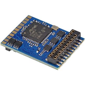
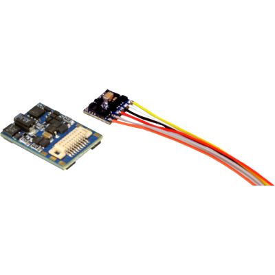
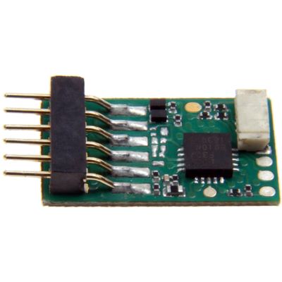
An H0 locomotive with a PluX22 interface requires a compatible PluX22 decoder. A Next18 decoder cannot be inserted directly.

Key Point

The locomotive decoder is responsible for motor control and vehicle functions.

What Is a Function Decoder?

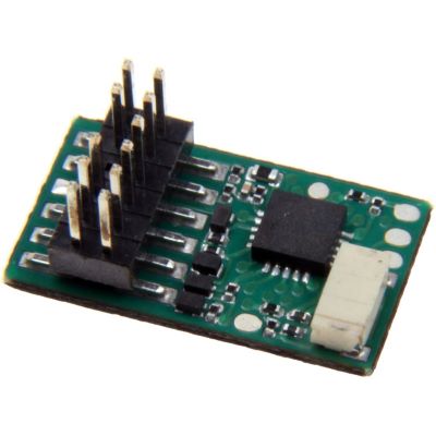
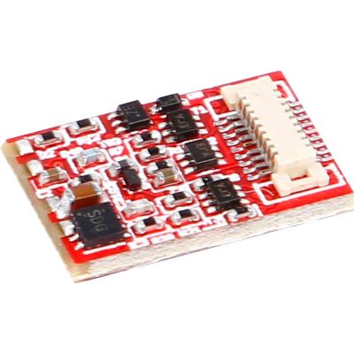
A function decoder also receives digital commands, but it does not have a regulated motor output. It is used when only lighting, couplers, servos or other functions need to be switched.

Where Is It Used?

Typical applications include driving trailers, passenger coaches, intermediate railcar coaches, cranes, snowploughs and functional models.

Practical Example

In a driving trailer, the decoder independently switches white headlights, red tail lights and interior lighting.

Key Point

A function decoder switches functions, but it does not control a traction motor.

What Is an Accessory Decoder?

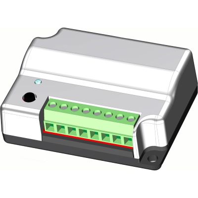
An accessory decoder receives accessory commands from the command station and switches stationary electrical loads. Depending on its design, it provides short pulses, continuous switching voltages, relay contacts or control signals for servos and motor drives.

Which Loads Are Compatible?

Twin-coil drives, motorised turnouts, servos, colour-light signals, semaphore signals and lighting require different types of outputs.

Practical Example

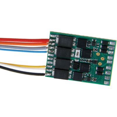
A four-output magnetic-accessory decoder can operate four twin-coil turnout drives through four digital addresses.

Key Point

An accessory decoder controls equipment that is permanently installed on the layout.

What Is a Feedback Module?

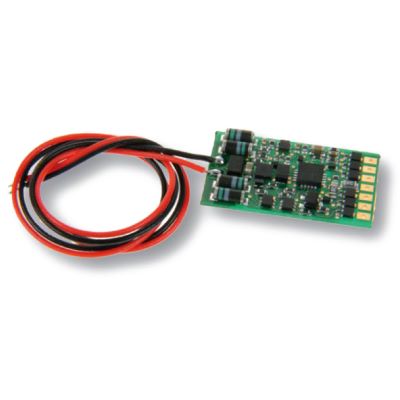
A feedback module detects states on the layout and transmits them to the command station or a computer. It can evaluate current consumption, ground contacts, reed contacts, switches, push buttons or other sensors.

Why Is Feedback Important?

Automatic operating sequences require reliable information about whether a track section is occupied or a contact has been triggered.

Practical Example

When a locomotive enters a monitored section, a current sensor detects the electrical load and reports the track as occupied.

Key Point

A feedback module returns information from the layout to the control system.

What Is a Booster?

A booster is the power stage of a digital system. It receives the digital control signal from the command station and converts it into a robust track signal for locomotives, decoders, lighting and other electrical loads.

When Is a Booster Required?

An additional booster is useful when the command station does not provide enough power or when several separate short-circuit and supply districts are required.

Practical Example

The main station and staging yard are supplied separately. A short circuit in the station therefore does not automatically shut down the entire layout.

Key Point

A booster provides more power, but it does not provide more decoder addresses.

What Is a Digital Bus?

A digital bus is a defined data connection between the command station and system devices. It transmits commands, feedback, configuration data and, in some systems, a limited supply voltage.

Which Bus Systems Are Available?

Common examples include LocoNet, s88 or s88N, XpressNet, R-Bus, CAN, ECoSlink and manufacturer-specific connections.

Practical Example

A feedback module detects track occupancy and sends the state to the digital command station through LocoNet or R-Bus.

Key Point

Connectors that look identical do not guarantee technical compatibility.

From operator command to track occupancy

How the Digital Components Work Together

On an expanded layout, commands travel from the command station to the electrical load, while feedback information travels back to the control system.

1

Command Station

Generates driving, function and accessory commands.

2

Booster

Provides electrical power for the track district.

3

Locomotive Decoder

Controls the locomotive motor and functions.

4

Accessory Decoder

Operates turnouts, signals and stationary accessories.

5

Feedback Module

Detects track occupancy and contacts.

6

Digital Bus

Transports the information back to the system.

What Is the Main Difference Between a Decoder and a Digital Bus?

A decoder receives a command and performs a specific task. A digital bus connects several devices and transports their data. It is the communication link, not the motor controller or switching output.

Consider installation space, voltage and current

Digital Technology for H0, TT, N, Z, 0, 1 and G

Many stationary modules can be used across different gauges. For vehicle decoders, however, the dimensions, motor current, interface and permitted track voltage are decisive.

Gauge Typical Decoders Common Interfaces Special Consideration
Z Micro and nano decoders Wires or specialist circuit boards Very limited space and low voltage
N Small micro decoders Next18, NEM 651 and PluX16 Check the dimensions precisely
TT Compact locomotive and function decoders Next18, PluX12 and PluX16 Check the installation position in the vehicle
H0 Standard, micro and sound decoders PluX22, 21MTC, NEM 652 and Next18 Wide selection for two-rail and centre-conductor systems
0 and 1 Powerful large-scale decoders Wires, screw terminals or circuit boards Consider the higher motor current
G and IIm Large-scale and high-current decoders Wires and screw terminals Outdoor operation and high electrical loads
Select data connections correctly

Digital Buses and Their Typical Tasks

A digital bus is often associated with a particular system family. Adapters or interfaces should only be used when technical compatibility is expressly supported.

Digital Bus Typical Devices Common Application Important Advice
LocoNet Handheld controllers, feedback modules and switching modules Uhlenbrock and compatible systems LocoNet-T and LocoNet-B are different.
s88 / s88N Feedback modules and contact detectors Märklin and compatible command stations An RJ45 connector does not mean Ethernet.
XpressNet Handheld controllers and interfaces Lenz and compatible DCC systems Check approved devices and pin assignments.
R-Bus Feedback and track-occupancy modules Roco Z21 systems Observe the module order and address.
CAN Command stations, boosters and operating devices Various system families CAN products are not automatically compatible.
ECoSlink Boosters, controllers and ESU modules ESU ECoS system family Other buses require suitable interfaces.
Compatibility before the number of features

Which Specifications Must Be Checked Before Buying?

The decoder with the most functions or the most powerful module is not automatically the right choice. Technical compatibility with the vehicle and digital system is decisive.

Interface

Next18, PluX12, PluX16, PluX22, 21MTC, NEM 651 and NEM 652 are different connector systems.

Digital Protocol

DCC, mfx, Motorola or Selectrix must be supported by both the command station and decoder.

Current Capacity

Motor and function current must not exceed the permitted values of the decoder or switching output.

Output Type

Lighting, servos, twin-coil drives and motor drives require different electrical outputs.

Digital Bus

Feedback modules, boosters and handheld controllers must use a bus connection that is compatible with the command station.

Current System

Two-rail and centre-conductor systems affect current collection, wheelsets, vehicle design and feedback technology.

Avoid unsuitable purchases and faults

Common Mistakes with Decoders and Digital Modules

Locomotive and Function Decoders Are Confused

A function decoder does not have a regulated motor output and cannot fully control a powered locomotive.

The Interface Is Selected Only by the Number of Pins

PluX22 and 21MTC both have many contacts, but they are mechanically and electrically completely different interfaces.

The Accessory Decoder Does Not Match the Drive

Twin-coil, servo and motorised drives require different output signals.

The Feedback Module Does Not Match the Track System

Current sensors, ground contacts and potential-free contacts require different wiring arrangements.

Booster Districts Are Not Separated Correctly

Electrical bridges can cause short circuits, equalising currents and unreliable operation.

A Bus Cable Is Confused with a Network Cable

An RJ45 connector provides no information about the protocol, pin assignment or electrical voltage.

Questions and Answers

FAQ About Locomotive Decoders, Modules, Boosters and Digital Buses

The following answers help to distinguish between the components and select the right digital equipment.

Can a locomotive decoder also switch lights and couplers?

Yes. In addition to the motor output, many locomotive decoders have several function outputs for lighting, smoke generators or digital couplers.

When do I need a function decoder?

A function decoder is required when a model has no motor or when additional functions need to be switched independently.

Can an accessory decoder operate every turnout?

No. The output must be suitable for the twin-coil, servo or motor drive used by the respective turnout.

What is the difference between an accessory decoder and a feedback module?

An accessory decoder executes a command. A feedback module instead detects a layout state and sends the information back.

When is a booster required?

A booster is required when the command station does not provide enough power or when several separate power and short-circuit districts are needed.

Does a booster increase the number of locomotive addresses?

No. A booster only increases the available electrical power. The number of addresses is determined by the command station and digital protocol.

Is s88N a normal computer network?

No. Although s88N commonly uses RJ45 connectors, it has its own protocol and electrical pin assignment.

Can I mix digital buses from different manufacturers?

Only when the manufacturers expressly provide shared compatibility or a suitable interface.

Which decoder fits an N scale locomotive?

The interface, installation space, height, motor current and digital protocol are decisive. Next18 and NEM 651 decoders are frequently used.

Do accessory decoders depend on the gauge?

Usually not directly. The voltage, output type, load capacity and compatibility with the digital system are more important.

Can a feedback module identify a locomotive?

A simple occupancy detector usually only recognises an electrical load. Additional compatible methods and system components are required for vehicle identification.

What should be purchased first?

First define the command station, digital protocol and vehicle fleet. Decoders, switching modules, feedback equipment and boosters can then be selected to suit the layout concept.

Select Digital Technology to Suit Your Model Railway

Discover further guides about digital command stations, decoders, current systems, gauges, layout planning and reliable digital operation.

Go to the Main Guide Page