1. Operation
A locomotive is selected and a driving command is entered using a handheld controller, display, smartphone or computer.

What does DCC mean, how does a locomotive recognise its driving command, and what are a digital command station, decoder, address and CV used for? This guide explains the widely used digital format step by step—from the first digital locomotive to a large automated layout.
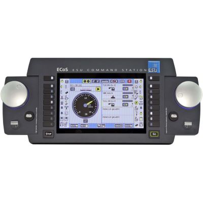
DCC stands for Digital Command Control. It is a standardised digital control method for model railways. A digital command station transmits electrical power and digital commands through the track. A decoder inside the locomotive receives these commands and converts them into speed, direction, lighting, sounds and other functions.
Every digital locomotive has its own address. The command station might, for example, send the instruction: “Locomotive 23 moves forwards at speed step 40 with its lights switched on.” Only the decoder with this address responds. Other vehicles on the same track ignore the command and retain their current state.
This allows several locomotives to operate independently on the same electrically connected track. One locomotive can shunt, a second can wait at the station and a third can haul a train along the main line. Basic DCC operation does not require automatic computer control or complicated block wiring.
The digital driving command passes through several components. Transmission is so fast and the commands are repeated so frequently that several vehicles appear to be controlled almost simultaneously.
A locomotive is selected and a driving command is entered using a handheld controller, display, smartphone or computer.
The command station converts the input into a DCC data packet containing the address, speed, direction and functions.
The internal or external booster supplies the digital track signal with the required electrical power.
The DCC signal travels through the rails and wheels to all connected vehicle decoders.
Only the addressed decoder executes the command and controls the motor, lighting, sound or other outputs.
The track acts as a shared transmission path. The locomotive address works in a similar way to a recipient address: all decoders receive the data, but only the addressed recipient responds.
The DCC track signal alternates between two polarities. The duration of these changes represents digital zeros and ones. They form data packets containing an address, an instruction and error checking.
Only a few coordinated components are required for initial operation. Feedback, computer control and extensive layout automation can be added later.
It generates the DCC commands, manages locomotive addresses and connects controllers, boosters, feedback modules and other layout components.
A rotary control, buttons, touchscreen or app can be used to select, accelerate and brake locomotives and operate their functions.
The decoder is installed inside the vehicle. It evaluates the data and controls the motor, headlights, cab lighting, couplings or sound.
A booster amplifies the digital track signal. It is required when the current demand or layout size exceeds the output of the command station.
Point, switching and signal decoders convert DCC commands into switching operations for solenoid accessories, lighting or signals.
Feedback modules inform the command station or control software about occupied track sections, contacts and other layout conditions.
In analogue operation, the track section is primarily controlled. With DCC, each individual vehicle is addressed by its own address.
| Feature | Analogue operation | DCC operation |
|---|---|---|
| Speed | Controlled by changing the voltage in the track section. | The decoder receives an individual digital driving command. |
| Several locomotives | Independent operation requires separate circuits or blocks. | Several addressed locomotives operate independently on the same track. |
| Lighting | Brightness often depends on the track voltage. | Lights can remain illuminated while stationary and can be switched separately. |
| Sound and functions | Available only to a limited extent or operated automatically. | Numerous functions can be operated directly using function keys. |
| Adjustment | Usually requires electrical or mechanical modifications. | Driving behaviour and functions are adjusted through decoder settings. |
| Automation | Possible using relays, switches and separate control systems. | Can be expanded flexibly using feedback modules, accessory decoders and software. |
The locomotive address determines which commands a decoder responds to. New decoders are often supplied with a standard factory address. Before operating several vehicles, each locomotive should be assigned its own address. Short addresses are typically within the range from 1 to 127. Many command stations and decoders also support long or four-digit addresses.
Speed steps divide the speed range into individual levels. DCC supports 14, 28 and 128 speed steps. Modern layouts generally use 28 or 128 speed steps. The command station and decoder must use the same setting so that driving behaviour and lighting operate correctly.
CV means Configuration Variable. CVs are memory locations inside the decoder. They store settings such as the address, minimum speed, acceleration, braking delay, maximum speed and basic operating options. These values normally remain stored even when there is no track voltage.
Decoders can be read and configured safely on a programming track. “Programming on Main” allows many values to be changed directly on the main track. Particular care must be taken to ensure that the correct locomotive address has been selected.
| Term | Simple meaning | Practical example |
|---|---|---|
| Address | Digital identifier of a decoder | Class 218 locomotive is assigned address 218 |
| Speed step | Digitally defined speed level | Speed step 20 of 128 |
| Function | Switchable decoder command | F0 lighting, F1 sound |
| CV | Stored setting value | CV 3 changes acceleration |
| RailCom | Optional return channel for DCC | Decoder reports its address |
With conventional DCC, the command station sends commands to the decoder. RailCom adds a return channel. Compatible decoders can send information back through the track. Compatible decoders, a suitable command station, boosters and, where required, RailCom detectors are needed.
DCC is not tied to a particular scale. The main differences concern decoder size, permitted motor current, track voltage and the required booster output.
DCC is possible but requires particularly small decoders. Compact wired decoders, NEM 651, Next18 or manufacturer-specific circuit boards are commonly used.
DCC is widely used in TT. Depending on the vehicle and its year of manufacture, Next18, PluX12, PluX16 or NEM 651 may be used.
H0 offers a particularly large selection of DCC command stations, locomotive and sound decoders, including PluX22, 21MTC and NEM 652 versions.
DCC can be used when the command station and vehicle decoder support it. Current pickup, pickup shoe and wheelsets must also be suitable for the centre-contact system.
DCC is also suitable for narrow-gauge railways. The limited space inside small vehicles determines the decoder, speaker and energy storage that can be installed.
Larger motors and extensive functions require decoders with sufficient current capacity and suitable function outputs.
DCC can control the traction motor, sound, smoke, lighting, servos and other functions. The total current demand must be calculated carefully.
Large-scale vehicles require powerful decoders, command stations and boosters. Long wiring runs and several trains also increase the current demand.
With a new digital vehicle, only the basic settings should initially be checked. Advanced motor, lighting and sound adjustments can then be made in small, documented steps.
Confirm that the command station transmits DCC and check which speed steps, programming methods and feedback functions it supports.
Check the decoder protocol, interface, current system, minimum radius and any special information provided by the vehicle manufacturer.
Place only the new vehicle on the programming or test track and check whether it responds to the standard address.
Choose a free, easily identifiable address and avoid duplicate addresses within the vehicle fleet.
Configure the minimum speed, acceleration, braking delay and maximum speed gradually.
Record the address, modified CVs, function keys, sound assignments and the date of the most recent programming.
Check the track voltage, selected address, protocol, current pickup and decoder connection. Then test the vehicle by itself on a short section of track.
The speed-step settings of the command station and decoder often do not match. Check whether 14, 28 or 128 speed steps are configured.
Check the motor connections and decoder settings. On many decoders, the direction can be changed using CV 29.
First remove all vehicles. Then check the track connections, points, reversing loops and decoder connection step by step.
Switch off the power immediately. Possible causes include an overloaded motor, incorrect wiring, a short circuit or an inadequately rated decoder.
Check the programming mode, locomotive address, CV range and write confirmation. Some settings require additional index CVs or manufacturer software.
Before buying, always check the supported protocol, decoder interface, available installation space, current capacity and required function outputs.
From compact handheld control to powerful network and multiprotocol command stations.
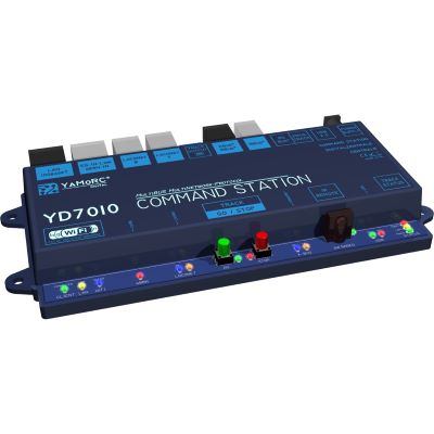
Modern DCC command station with network and WLAN connectivity.
View product →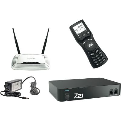
Network-capable DCC system with a convenient handheld controller.
View product →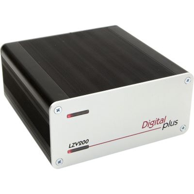
DCC command station with an integrated power amplifier.
View product →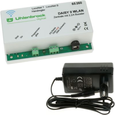
Compact DCC control system with a wireless handheld controller.
View product →
Powerful command station with a large control display.
View product →
Multiprotocol command station for extensive vehicle fleets.
View product →Space-saving decoders for NEM 651, Next18, PluX12, PluX16 and models without a plug-in interface.
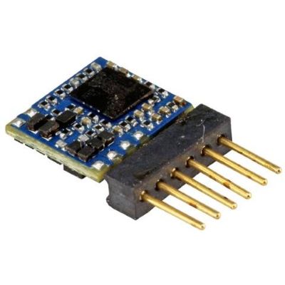
Compact DCC-only decoder for small vehicles.
View product →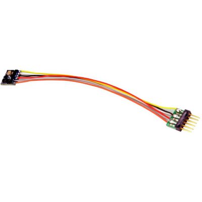
Multiprotocol decoder with a six-pin plug.
View product →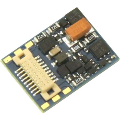
Compact multiprotocol decoder with Next18.
View product →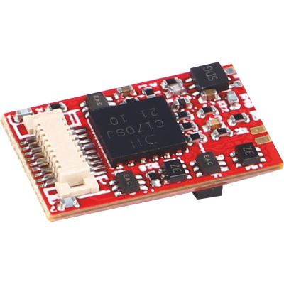
Next18 decoder for compact PIKO vehicles.
View product →
Compact DCC decoder with individual connection wires.
View product →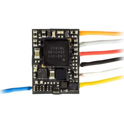
Subminiature decoder for small locomotives.
View product →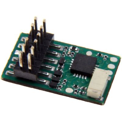
Compact decoder for prepared TT-scale vehicles.
View product →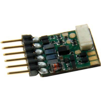
Six-pin decoder for small vehicle bodies.
View product →A selection for PluX22, 21MTC and the classic eight-pin NEM 652 interface.
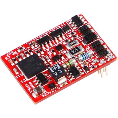
Modern multiprotocol decoder with PluX22.
View product →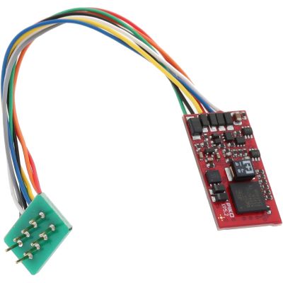
Eight-pin decoder for vehicles with a NEM 652 interface.
View product →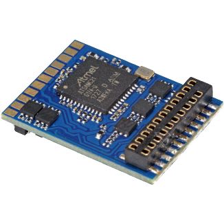
Multiprotocol decoder for vehicles with a 21MTC interface.
View product →
DCC-only decoder with a PluX22 interface.
View product →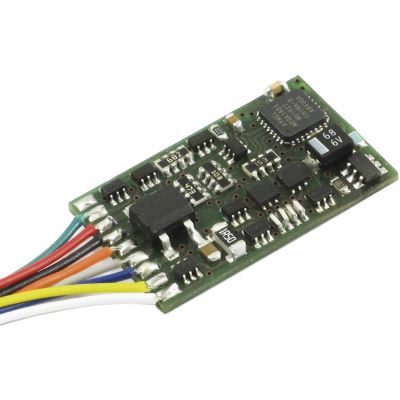
DCC locomotive decoder for eight-pin interfaces.
View product →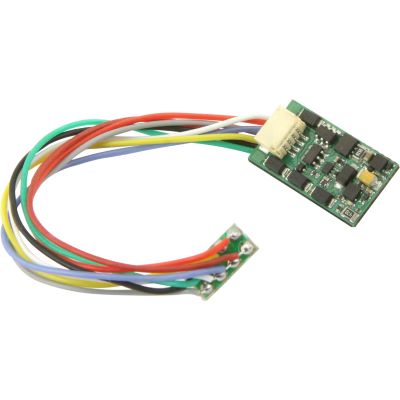
Multiprotocol decoder with a NEM 652 plug.
View product →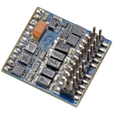
Function decoder for driving trailers and function models.
View product →Large-scale decoders for more powerful motors, sound, smoke, lighting and extensive additional functions.
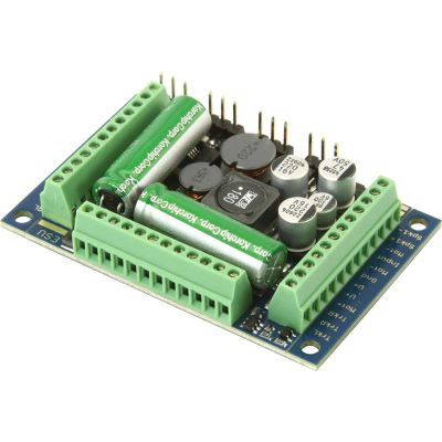
High-performance sound decoder with screw terminals.
View product →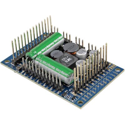
Large-scale sound decoder with pin headers.
View product →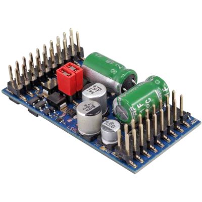
Powerful sound decoder for larger models.
View product →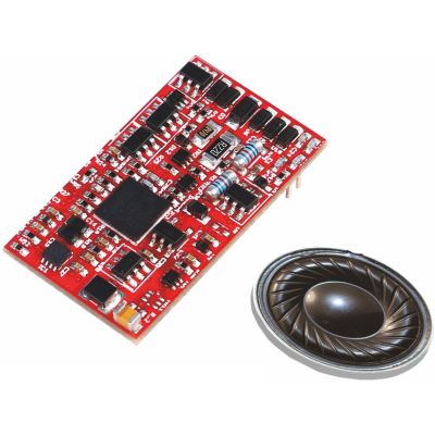
Vehicle-specific large-scale sound decoder.
View product →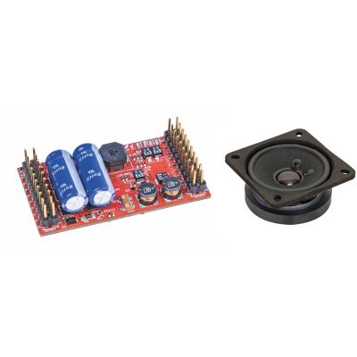
Sound decoder with a loudspeaker for large-scale models.
View product →DCC stands for Digital Command Control. It is a standardised method for digitally controlling model railway vehicles and accessories.
Yes. Each locomotive has its own decoder address, allowing its speed, direction and functions to be controlled independently.
No. DCC is a digital data format. DC means direct current and is commonly used for analogue two-rail vehicles in model railways.
Yes, provided that the command station and decoder support DCC. The vehicle must also have a suitable centre-contact current pickup and compatible wheelsets.
A CV is a stored setting value. CVs are used to adjust the address, driving behaviour, lighting and various decoder functions.
No. DCC works without RailCom. The extension is required when compatible decoders are to send information back through the track.
DCC is not tied to a particular plug. DCC decoders are available for Next18, PluX, 21MTC, NEM 651, NEM 652 and with individual connection wires.
An analogue locomotive should not be operated on a digital layout without first checking its suitability. A compatible digital decoder is required for safe, regular operation.
Often yes, provided that all devices support the DCC standard and their electrical specifications, interfaces and digital buses are compatible.
For a small layout, a clearly arranged command station with a handheld controller is usually sufficient. Important features include simple operation, a programming track, adequate power and useful expansion options.
Discover more essential information about digital command stations, locomotive decoders, interfaces, current systems, gauges, layout planning, wiring and fault diagnosis.