Control
A handheld controller, touchscreen, app or computer records the selected locomotive, speed and function.

A digital command station receives commands from a handheld controller, touchscreen, smartphone or computer and translates them into digital signals for locomotives, turnouts, signals and accessories. Learn how decoder addresses, DCC, mfx, boosters, programming tracks and feedback work together.





 ```
```
A digital command station connects layout operation with the decoders in locomotives and accessories. When you turn the speed controller, activate a function or select a turnout, the command station converts the action into a digitally encoded command.
This command is transmitted together with electrical power through the track or an accessory bus. Every locomotive decoder has its own address. The command station can therefore control several locomotives independently, even though all vehicles are standing on the same electrically connected track.
For example, when locomotive address 23 is selected, only the decoder with this address responds to speed, direction, lighting or sound commands. The other vehicles receive the signal as well but do not execute it.
Turnouts, signals, uncouplers and lighting can also have digital addresses. Stationary switching and accessory decoders are used for this purpose. The command station therefore not only manages trains but can coordinate the entire technical layout.
The digital command station converts an operator input into an addressed data packet, transmits it together with track power to all connected decoders and ensures that only the selected vehicle or accessory executes the command.
The individual devices may be combined in one housing or distributed across several components. The basic signal path nevertheless remains comparable.
A handheld controller, touchscreen, app or computer records the selected locomotive, speed and function.
The command station combines the operator input with the locomotive address and the appropriate digital protocol.
An integrated or external booster converts it into a robust digital signal for the track.
The addressed decoder recognises its address and controls the motor, lights, sound or switching outputs.
Occupancy detectors, contacts or compatible decoders can report states back to the command station or control software.
The range of functions extends from simple manual locomotive control to a graphical track-diagram panel with routes, feedback, network access and automated operating sequences.
Every locomotive is assigned its own address. Speed, direction and functions can be changed independently of other vehicles on the same track.
One locomotive can perform shunting movements while another train waits at the station with its lights switched on.
Digital decoders provide function keys for headlights, tail lights, horns, engine sounds, braking, announcements or cab lighting.
The vehicle, decoder and command station must support the required range of functions.
Magnetic-accessory or switching decoders have their own addresses. The command station sends the command, and the decoder then operates the connected drive.
Several turnouts and signals can be combined to form a route.
Addresses, acceleration, braking delay, maximum speed and function outputs can be changed through the programming track or the main track.
Locomotive address, speed curve, light mapping, volume and motor control.
Feedback modules detect occupied track sections, contacts or other layout states and transmit this information to the command station or computer.
Block operation, staging yards, shuttle trains and automatic routes.
The command station or its booster stage monitors the output and switches off in the event of a short circuit. Larger layouts are divided into several power districts.
A more powerful booster increases the available electrical output, not the number of available digital addresses.
The command station and decoder must support at least one common digital protocol. The protocol is not the same as the gauge or the two-rail or centre-conductor system.
| Term | Function | Typical Use | Selection Advice |
|---|---|---|---|
| DCC | Standardised transmission of driving, function and switching commands | Especially widespread on two-rail layouts | The command station and decoder must support DCC. |
| mfx | Bidirectional protocol with convenient vehicle registration | Primarily Märklin digital systems | Automatic registration requires compatible devices. |
| Motorola | Digital format for older and existing Märklin vehicles | Existing Märklin layouts | The address range and number of functions may be limited. |
| RailCom | Returns compatible information from the decoder | Compatible DCC systems | The booster and feedback components must also be compatible. |
| Multi-protocol | Supports several digital languages | Mixed vehicle fleets | System buses may still remain manufacturer-specific. |
The available connections determine how effectively the system can be expanded later. Feedback, booster and network interfaces should be considered early, especially when automation is planned.
| Connection | Function | Application | Planning Advice |
|---|---|---|---|
| Main track | Transmits driving commands and track power | Normal layout operation | Multiple feed points improve the power supply. |
| Programming track | Reads and writes decoder settings | Addresses and configuration values | Separate it safely from the main track electrically. |
| Booster bus | Transmits the digital signal to additional power stages | Large layouts and separate power districts | The booster and command station must be compatible. |
| Feedback bus | Transmits track occupancy and contact information | Automation and staging yards | Select the bus standard before purchasing modules. |
| LAN or Wi-Fi | Connects apps, computers and wireless devices | Mobile operation and software control | Local operation usually works without internet access. |
| Handheld controller bus | Connects additional operating devices | Multiple operating positions | It is often tied to a particular system family. |
The decision should not be based solely on display size or output current. The existing vehicle fleet, required protocols, preferred operating method, feedback bus, network features and planned future expansion are all important.
A compact system with a clear handheld controller and simple decoder programming is often sufficient for a few trains running at the same time.
DCC or mfx, accessory control and an expansion connection.
Anyone planning to add feedback, smartphone control, several handheld controllers or computer control later should select an expandable network and bus system.
LAN or Wi-Fi, a booster bus and a feedback interface.
Large vehicle fleets, staging yards and automatic routes require a powerful system architecture with several power districts.
Computer connection, numerous feedback modules, routes and several boosters.
| Gauge | Typical Focus | Important Criteria | Special Consideration |
|---|---|---|---|
| Z and N | Compact vehicles and decoders | Suitable track voltage and sensitive short-circuit detection | Avoid excessive voltage. |
| TT | Multi-train operation in a medium-sized space | DCC, feedback and expandable handheld controllers | Plan the output according to the actual number of trains. |
| H0 DC | Wide selection of manufacturers and decoders | DCC, RailCom, network and booster bus | Select the feedback system early. |
| H0 AC | Centre-conductor system with mfx and Motorola | mfx, DCC and Märklin system connections | Check the current system and protocol separately. |
| 0 and 1 | Higher motor and sound current | Powerful booster and adjustable voltage | Consider the current consumption of every vehicle. |
| G | Garden railways and long cables | High power, wireless operation and robust components | Consider cable cross-sections and outdoor operation. |
Always follow the instructions provided by the respective manufacturer. A clearly arranged test setup makes troubleshooting easier and prevents several unknown sources of error from occurring at the same time.
Determine whether the layout uses two-rail or centre-conductor track and which digital protocols the existing decoders support.
Use the intended or expressly approved power supply with the correct voltage and output.
Begin with a short section of track without turnouts, feedback modules or boosters. This keeps the first test straightforward.
Select the address manually or use a supported automatic registration process. Begin by testing at low speed.
Separate the programming section electrically from the main track and initially change only one simple decoder address.
Connect turnout decoders, feedback modules, network devices and boosters one after another and test the system after every step.
Change connections only while the power supply is switched off. The main track, programming track and booster districts must not be bridged unintentionally. In the event of repeated short circuits, check the vehicles, track and wiring first instead of repeatedly switching the command station back on.
The systems differ in their operation, digital protocols, feedback buses, wireless technology and expandability. Within each manufacturer’s system family, you will find compatible command stations, handheld controllers, boosters, decoders and feedback modules.
Central Station, Mobile Station, mfx, Motorola and DCC.
Network-enabled DCC control with Wi-Fi, app and feedback.
ECoS multi-protocol command stations, CabControl and wireless controllers.
SmartControl WLAN, boosters and digital starter solutions.
Intellibox, DAISY II, Wi-Fi and LocoNet system technology.
DCC command stations, amplifiers, handheld controllers and XpressNet.
DCC command stations, universal boosters and feedback technology.
Powerful DiMAX systems and wireless controllers for G scale.
The selection includes compact DCC solutions, network command stations, multi-protocol devices and powerful systems for large layouts.
Multi-protocol
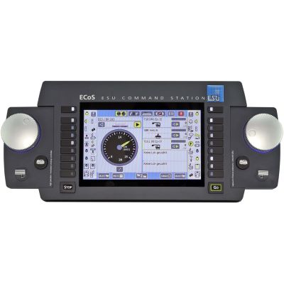
Multi-protocol command station with a large display, two speed controllers and an integrated booster.
View Command Station →
mfx · DCC
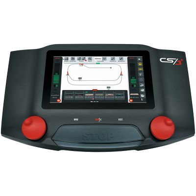
System command station with touchscreen, speed controllers, track-diagram panel and versatile connections.
View Command Station →
CS3
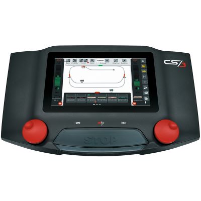
Graphical control of locomotives, accessories and routes within the Märklin system.
View Command Station →
Z21 · WLAN
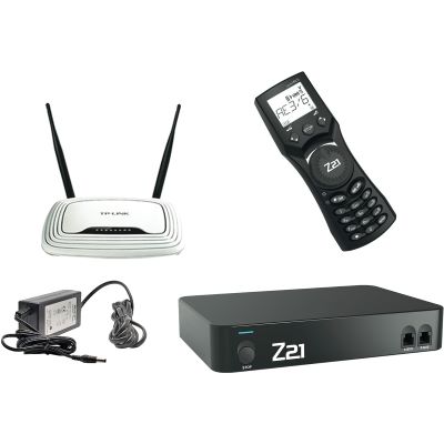
Network-enabled digital control system with a Wi-Fi router and mobile handheld controller.
View Digital Set →
DCC · Network
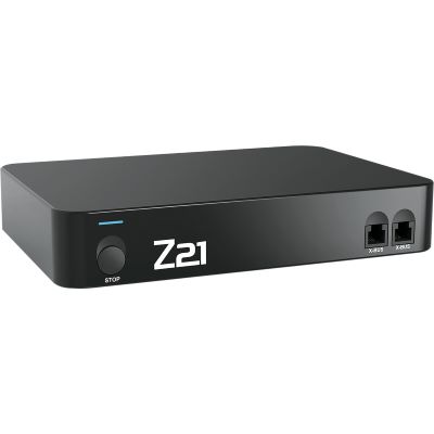
DCC network command station with numerous bus, feedback and expansion connections.
View Command Station →
DCC · WLAN
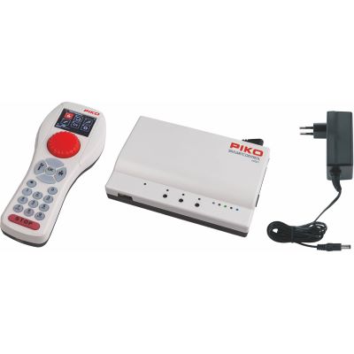
Wirelessly operated DCC base system for an expandable digital layout.
View Digital Set →
Intellibox

Digital command station with physical speed controllers and versatile system connectivity.
View Command Station →
DCC · WLAN
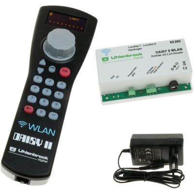
Compact DCC system with a wireless handheld controller.
View Digital Set →
DCC · Wireless
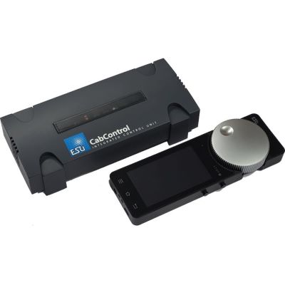
DCC control system with a mobile wireless controller for layout operation.
View Digital Set →
DCC · 5 A
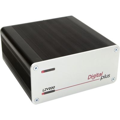
DCC command station with an integrated power amplifier as the system base.
View Command Station →
Beginner
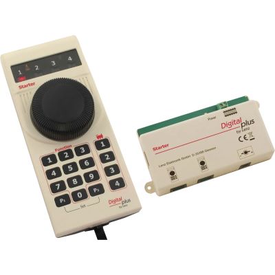
Clear and straightforward basic DCC equipment for getting started digitally.
View Digital Set →
DCC · WLAN
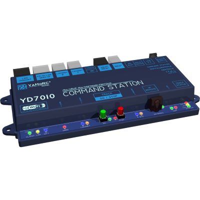
Network-capable DCC command station for flexible feedback and computer systems.
View Command Station →Handheld controllers are the user interface of the digital command station. Depending on the model, they require a compatible base station, system connection or Wi-Fi connection.
mfx · DCC
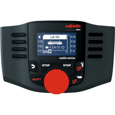
Compact control for locomotives and digital magnetic accessories.
View Handheld Controller →
WLAN
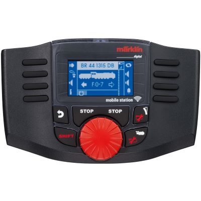
Wireless handheld controller for compatible Märklin digital systems.
View Handheld Controller →
Wireless Controller
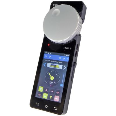
Mobile wireless controller for compatible ECoS, Z21 and CS3 systems.
View Handheld Controller →
DAISY II
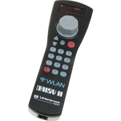
Wireless handheld controller for compatible Uhlenbrock system solutions.
View Handheld Controller →
Z21
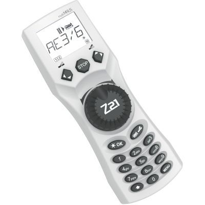
Handheld controller for driving, switching and programming within the Z21 system.
View Handheld Controller →
G · Wireless
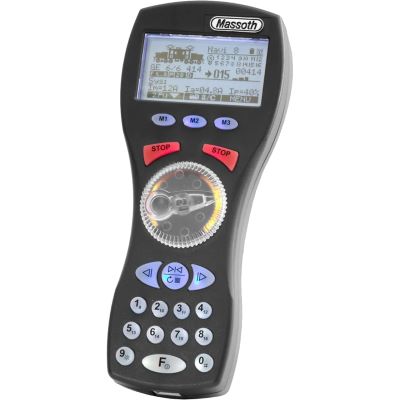
Wireless handheld controller for compatible DiMAX and garden railway systems.
View Handheld Controller →These components expand the digital command station with additional power districts, digital accessory control and the detection of track occupancy or contacts.
Switching
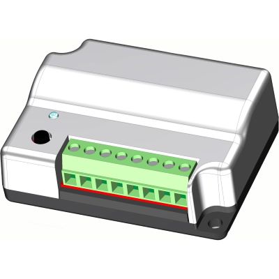
Digital switching of turnouts, signals and magnetic accessories.
View Module →
8 Outputs
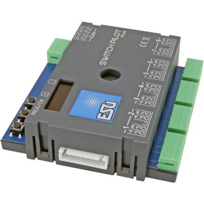
Configurable accessory decoder for turnouts and stationary electrical loads.
View Module →
m83
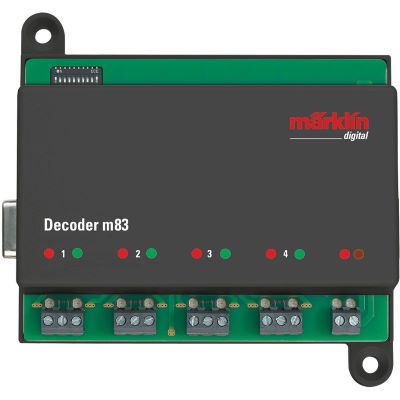
Switching module for turnouts and other digital magnetic accessories.
View Module →
s88N
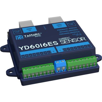
Sixteen feedback inputs for occupancy detection and automation.
View Feedback Module →
Z21 Feedback
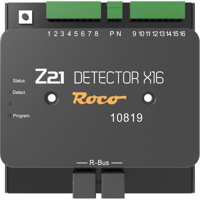
Track occupancy detector for staging yards and automatic driving sequences.
View Feedback Module →
Z21 Booster
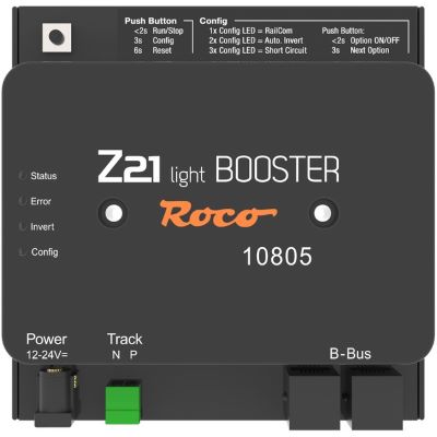
Additional power supply for a separate digital layout district.
View Booster →
3.5 A Booster
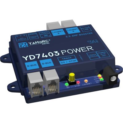
Universal booster for additional digital power and separate power districts.
View Booster → Feedback
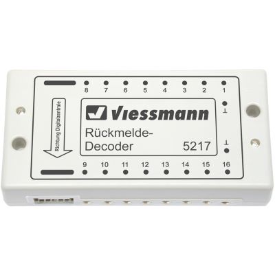
Feedback module for contacts, track occupancy and control tasks.
View Feedback Module →Not every fault means that the command station is defective. The causes are often found in vehicles, track, addresses, wiring or an overloaded power supply.
Remove all vehicles and connect only an empty test track. Then reconnect the vehicles and layout sections one at a time.
Check the track voltage, address, digital protocol, current pickup and decoder connection. Test the locomotive on its own wherever possible.
Several decoders are probably using the same address. Assign a unique address to every vehicle.
The power demand may exceed the command station’s capacity. Include sound, lighting, smoke generators and stationary vehicles in the calculation.
Check the router, network connection, IP settings and local device permissions.
Check the module order, addresses, bus connection, common ground and detection sections.
The answers summarise the most important basics relating to decoder addresses, booster power, programming tracks, Wi-Fi and automatic control.
Not completely. A power supply provides the energy, while the command station generates the digital commands. An integrated or external booster stage combines the signal and power for the track.
Every locomotive has a decoder with its own address. Only the addressed decoder executes the respective driving or function command.
Yes. For independent digital operation, every motorised locomotive requires a decoder that is compatible with the motor, current system and protocol.
The command station sends the command. The actual electrical control is normally performed by a turnout or magnetic-accessory decoder.
The command station generates and manages the commands. The booster amplifies the digital signal and supplies power to a track district.
An additional booster is required when the total current exceeds the command station’s output or when the layout is to be divided into separate short-circuit and power districts.
Decoder addresses and settings can be read or changed there without accidentally programming other vehicles on the layout.
No. A layout can be operated entirely with wired handheld controllers. Wi-Fi enables additional mobile operating devices.
Many command stations can be used across different gauges. However, the track voltage, output power and decoders must be suitable for the respective gauge.
No. DCC is a digital data protocol. Direct current or two-rail describes the track and current-collection system.
Often yes, provided that the protocol, bus, interface and electrical specifications are compatible. Manufacturer-specific system buses must be checked separately.
Not by itself. Automatic operation requires feedback modules, detection sections, route logic and, where applicable, a computer or integrated automation functions.
Discover digital command stations, handheld controllers, boosters, feedback modules, decoders and further essentials for reliable digital layout operation.