Identify the Decoder
Determine the manufacturer, decoder family, interface, vehicle model and available documentation.

After unsuccessful function mapping, incorrect motor settings or an unknown locomotive address, a controlled decoder reset can restore a defined factory configuration.
The exact decoder is crucial, however. ESU, PIKO, Märklin, ZIMO, Lenz and Uhlenbrock do not use the same reset procedure for every decoder family. The rule is therefore simple: identify and back up first – reset afterwards.
A decoder reset replaces some or all stored settings with default values defined by the manufacturer or decoder project. This may restore the locomotive address, acceleration, braking delay, maximum speed, motor control, lighting assignments, function mapping or volume to predefined settings.
A reset is therefore not a repair. If the locomotive runs badly because of dirty wheels, interrupted current pickup, a stiff gearbox, incorrect wiring or a damaged motor, these causes will still be present after the reset.
CV8 is particularly important. When CV8 is read from a DCC decoder, it normally returns the manufacturer ID. Writing a manufacturer-defined reset value to CV8 does not permanently replace that manufacturer ID. The written value is interpreted by suitable decoders as a command.
This is where one of the most common mistakes occurs: CV8 = 8 is used by many decoder families, but it is not a safe universal recommendation for every digital component. Decoder families, OEM versions, sound projects and older products can use different procedures.
Read CV8 first where supported, identify the manufacturer and decoder family and compare the result with the decoder and vehicle documentation. With factory-fitted sound locomotives, always include the vehicle documentation and project-specific information as well.
A reset can take only seconds. Reconstructing a lost configuration afterwards can take considerably longer.
Determine the manufacturer, decoder family, interface, vehicle model and available documentation.
Record at least the address, CV29, driving values, volume and any unusual function assignments.
When using LokProgrammer, SmartProgrammer or another compatible manufacturer tool, save the existing decoder project whenever possible.
Inspect wheels, pickup shoe, gearbox, motor, wiring and the vehicle circuit board. A reset cannot repair a hardware fault.
Place only the affected vehicle on a clean, electrically isolated programming track.
After switching off the power, allow enough time for installed energy-storage modules to discharge before restarting.
This table is a guide and not a replacement for the current decoder instructions. OEM decoders in particular can contain project-specific factory settings.
| Manufacturer | Typical Reset Method | Important Afterwards |
|---|---|---|
| ESU | Many LokPilot and LokSound families use value 8 written to CV8 in DCC mode. The LokProgrammer software can also provide a reset function. | OEM and sound-project versions may restore their own project-specific default values. |
| ZIMO | CV8 = 8 is the normal factory-reset command documented for many current ZIMO decoder families. | Other values written to CV8 can have ZIMO-specific functions. Do not confuse special commands with a standard reset. |
| Lenz | Depending on the GOLD, SILVER or Standard decoder family, documentation may specify CV8 with value 8 or value 33. | The exact decoder instructions are essential. On some families, connected SUSI modules or parts of a speed curve may not be included in the reset. |
| Märklin | For suitable mfx vehicles, prefer the reset command in a compatible Central Station or Mobile Station. Depending on the decoder instructions, mLD and mSD families may offer additional programming methods. | The vehicle may have to register with the mfx system again. |
| PIKO | Identify the SmartDecoder generation first. Many compatible SmartDecoder XP versions use CV8 = 8, while project management and reset functions may also be available through the SmartProgrammer. | XP, sound and OEM projects can contain different project-specific defaults. Use the documentation for the exact decoder or vehicle. |
| Uhlenbrock | The procedure is strongly decoder-dependent. Some IntelliDrive families use CV8 or CV59 with selectable reset ranges, while older products can use different documented procedures. | Never transfer a reset command from an unrelated or older decoder manual to another model. |
| TILLIG Vehicle | Identify the manufacturer of the decoder actually installed in the vehicle. | The vehicle brand and electronics manufacturer may be different. |
| OEM Sound Decoder | Consider the vehicle documentation and decoder project together. | A factory reset can restore mapping, volume and motor settings to values defined specifically for that vehicle project. |
Remove the vehicle from the main layout and place it alone on a clean, electrically isolated programming track.
Match the decoder family, manufacturer information and vehicle documentation unambiguously.
Document the address, CV29, driving parameters, mapping and sound settings or save the project file.
Use the command station's reset menu, the manufacturer's programmer software or an explicitly documented CV command.
Write the documented reset value only once. Do not experiment with additional unknown values.
Remove power briefly. If an energy-storage module is installed, allow sufficient time for it to discharge.
Test the factory address specified by the instructions, direction of travel, lighting and a slow test run without attaching a long train.
Reconfigure the address, acceleration, braking, motor control and function mapping step by step and test after every change.
Once the decoder manufacturer is known, the relevant brand pages provide access to compatible decoders, programmers, digital command stations and accessories for reconfiguration.
The reset method depends primarily on the decoder rather than the scale. Vehicle size, current consumption, interfaces and additional functions do, however, influence the checks that should be performed afterwards.
| Gauge World | Typical Characteristic | Checks After the Reset |
|---|---|---|
| Z Gauge | very small decoders and sensitive current collection | clean the contacts and begin with a very slow test run |
| N Gauge | Next18, NEM 651 and compact micro decoders | observe lighting, direction of travel and heat generation |
| TT / TTe | limited installation space, often Next18, PluX12, NEM 651 or compact decoders | test motor operation and function outputs individually |
| H0 / H0e / H0m / H0f | wide variety including NEM 652, Next18, PluX and 21MTC | test the digital system, sound, lighting and additional functions separately |
| Gauge 0 | more powerful motors and additional function outputs | check motor current, couplers, sound and AUX outputs |
| Gauge 1 / G | large-scale decoders, smoke generators and high loads | perform the first test without a train, with moderate volume and low load |
Do not automatically assume address 3. Check the decoder instructions, reset status, active protocol and actual factory address.
Check for an old or incorrect locomotive entry and restart automatic registration according to the command station instructions.
A sound project can contain its own factory function assignments. Compare the saved project or restore the correct project file.
Check decoder orientation, the vehicle circuit board and wiring. A reset cannot correct an incorrectly inserted decoder.
Inspect the wheels, track, gearbox, current pickup and motor. Persistent jerking is often not purely a CV problem.
Switch off track power immediately. Check motor current, wiring, lighting and possible short circuits. Do not continue resetting the decoder.
A programming device is particularly useful when a complete project should be backed up before resetting, mapping needs to be restored afterwards or a decoder should be tested outside the locomotive.
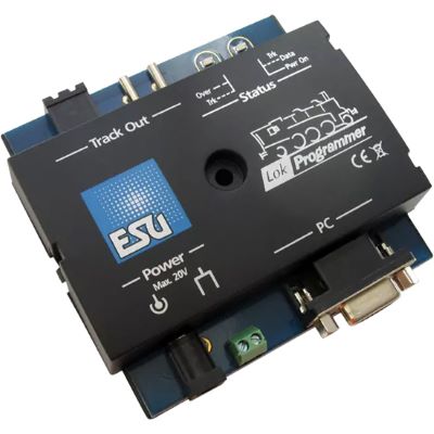
Save, configure and restore compatible LokPilot and LokSound decoder projects.
View Product →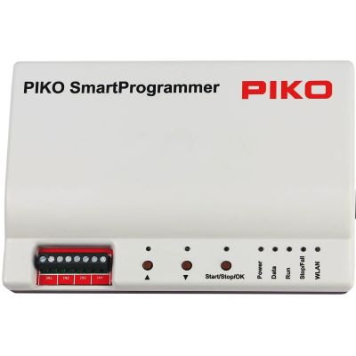
Conveniently manage settings and sound projects for compatible PIKO decoders.
View Product →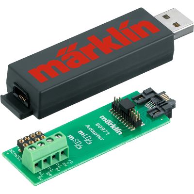
PC configuration for compatible Märklin retrofit decoders and preparation of decoder projects.
View Product →
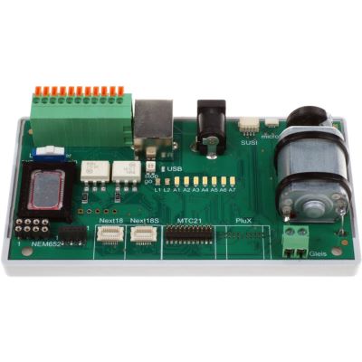
Test motor and function outputs and several common decoder interfaces outside the locomotive.
View Product →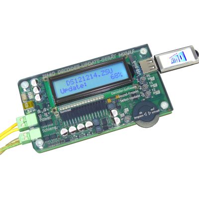
Program and update compatible ZIMO decoders and manage suitable sound projects.
View Product →The product search checks current English product categories and manufacturer pages at Modellbahnshop. Every discovered product page is checked before display. Products with an archive notice are excluded, product images are normalised to the 400-pixel shop version and delivery or stock information is deliberately not displayed on this landing page.
Live checking will begin when you approach this section.
Do not immediately start with complicated function mapping. First test the address, direction of travel and basic driving behaviour. Then configure acceleration, braking delay, motor control, lighting and function mapping. Extensive sound or specialist functions should come last.
There is no safe universal reset value for every decoder. Many decoder families use value 8 written to CV8, while other manufacturers or decoder families may use different values, ranges or menu commands. The instructions for the exact decoder always take priority.
When CV8 is read, it normally returns the manufacturer ID. A reset value written to CV8 is interpreted as a command and is not permanently stored as the new manufacturer ID.
Many DCC decoders return to address 3 after a factory reset. OEM decoders, special projects and other digital protocols can use a different default address, so always check the decoder instructions.
A normal factory reset often does not erase the sound file itself. Mapping, volume and other project values can, however, return to defaults defined by the sound project.
Suitable mfx vehicles can be reset using the reset function of a compatible Märklin Central Station or Mobile Station. Depending on the decoder, another documented method may also exist. A new mfx registration may be required afterwards.
In that case the problem is less likely to be purely a programming issue. Current pickup, wheels, pickup shoe, motor, gearbox, wiring and the vehicle circuit board should be checked technically.
A reset command documented by the manufacturer is an intended decoder function. Unknown CV commands, incorrect voltages, short circuits and repeated experimentation with undocumented values should be avoided.
Not necessarily. On some decoder families, connected SUSI modules are explicitly not included in the normal locomotive decoder reset.
Some decoder families provide partial resets or selectable configuration ranges. These functions are manufacturer-specific and must be checked in the relevant decoder instructions.
A manufacturer-specific programmer is particularly useful when complete projects need to be backed up, sound files managed, extensive function mapping edited or several decoders maintained regularly.
On DCC decoders, reading CV8 can provide an important clue because it normally returns the manufacturer ID. It does not, however, automatically identify the exact decoder family.
If the existing configuration can still be read, yes. At minimum, record the address, CV29, important driving values and function assignments. With a suitable programmer, save the complete project whenever possible.
The comprehensive Model Railway Guide connects decoders, digital command stations, interfaces, electrical systems, vehicles, maintenance and layout planning into one complete knowledge base.