Locomotive backwards, front headlight correct
The motor is running against the lighting logic. Check the orange and grey motor wires, plug orientation or a separate motor-reversal setting.

If the command station shows “forward” while the locomotive moves backwards, the cause may be CV 29, reversed motor wires, an incorrectly orientated plug or an unsuitable definition of the vehicle front. The decisive question is whether the headlights and tail lights also respond incorrectly.

If the locomotive moves backwards in response to a forward command and the direction-dependent lamps also illuminate at the wrong end of the vehicle, Bit 0 in CV 29 can be toggled in DCC operation. This setting reverses both the digital direction and the direction-dependent lighting functions.
If only the motor runs in the wrong direction while the white headlight already illuminates at the intended front of the vehicle, the motor wires have probably been reversed. On a freely wired decoder, the orange and grey motor wires are swapped after the power has been disconnected completely. Some decoder families alternatively provide a separate motor-reversal setting.
If only the lighting appears at the wrong end while the locomotive moves correctly, this is not a direction error. In that case, inspect the lighting outputs, white and yellow wires or the function mapping .
On a steam locomotive, the smokebox door is usually considered the front. On a multiple unit, cab 1 is often used. Some diesel prototypes were routinely operated with the long bonnet leading. The model instructions, cab numbers and intended operating concept remain decisive.
The motor is running against the lighting logic. Check the orange and grey motor wires, plug orientation or a separate motor-reversal setting.
The motor and lighting are reversed together. With DCC, CV 29 Bit 0 is the typical correction.
The motor direction is correct. Check the white and yellow lighting wires, vehicle circuit board or direction-dependent mapping.
The normal locomotive direction remains correct. Check the direction entry in the consist or Bit 7 of the DCC consist address.
Under the basic DCC definition, CV 29 Bit 0 concerns digital direction. Treat the analogue mode, track polarity and manufacturer-specific parameters separately.
Wires may be trapped or a plug may have become loose. Open the vehicle immediately and inspect it with the power switched off.
Set the command station to a low speed step and an unambiguous forward direction.
Determine which cab or end of the locomotive is leading.
Check whether the white headlight illuminates at the moving front.
Change the CV, motor connection or lighting mapping individually and deliberately.
Basic DCC functions are comparable, but additional motor and lighting reversal options differ between decoder families.






CV 29 contains several settings in a single value. In addition to direction, it may contain settings for speed steps, analogue operation, RailCom, the speed curve and short or long addressing. CV 29 must therefore not be replaced with an arbitrary value from a table.
To reverse only the DCC direction, toggle Bit 0. Add 1 when the current value is even, or subtract 1 when it is odd. The calculator performs exactly this change and leaves every other bit untouched.
This method is suitable when the direction and direction-dependent lighting must be reversed together. It is not automatically the best solution when only the motor wiring is incorrect.
Read the current CV 29 value and toggle Bit 0 deliberately.
The new value enables only the reversed DCC direction.
| Installation type | Typical symptom | Appropriate correction |
|---|---|---|
| Decoder with loose wires | Motor runs against the already correct lighting direction | Swap the orange and grey motor wires after disconnecting every source of power |
| NEM 652 plug | The motor and lighting behave unexpectedly after installation | Compare the pin-1 markings on the plug and socket with the power switched off |
| Next18, PluX or 21MTC | Several functions are missing after installation | Check the seating, orientation and possible offset contacts; do not rotate or force the decoder |
| Factory-fitted vehicle circuit board | Motor and lighting can be inverted separately | Use the manufacturer-specific software or decoder option |
| Red and black DCC track wires | Attempting to reverse the direction by swapping them | This is unnecessary; the digital direction is defined by the driving command |
| Märklin mLD3 or mSD3 | Only the motor or lighting direction is wrong | Check the decoder family's separate motor- or lighting-inversion options |
Check the cab, locomotive markings and model instructions, then document the intended forward end.
Select a low speed step and move the locomotive in both directions without any coaches attached.
Determine whether the white headlight matches the actual movement or the direction command.
Read and save CV 29 and, where appropriate, the complete decoder project.
Use a combined reversal through CV 29 or a separate motor- or lighting-direction correction.
Either write a CV value or alter the wiring, but do not do both at the same time.
Check the motor, headlights, tail lights, sound sequence and braking functions.
Align the command station, locomotive card and consist settings with the new definition of the vehicle front.
In DCC, Bit 7 in CV 19 can reverse the direction within a consist address. The command station may also define the locomotive as reversed inside the consist.
CV 29 Bit 0 defines the digital direction. DC or AC analogue operation follows polarity and manufacturer-specific settings.
After reversing the motor, retest braking, door and cab sequences. Sound logic and direction may be linked in the project.
Do not reverse the driving direction again. Correct the lighting wires, circuit-board assignment and function mapping separately.
The motor and function decoders may use separate direction values or decoder locks. Check both projects individually.
The reset removed the individual direction reversal. Restore the saved project or documented CV value.
| Gauge | Typical installation | Important consideration |
|---|---|---|
| Z / N | Direct wiring, NEM 651 or Next18 | Wires and solder pads are extremely small; avoid resoldering the motor wires unnecessarily |
| TT | PluX12, Next18 and NEM 651 | Check the circuit-board pin assignment and decoder instructions together |
| H0 | NEM 652, PluX22, 21MTC and Next18 | The widest variety of DCC, mfx, Motorola and OEM circuit boards |
| H0e / H0m | Micro decoders and direct wired connections | Allow for extremely limited installation space despite the H0 scale |
| 0 / 1 / G | High-output decoders and screw or solder connections | Check multiple motors, servos, lighting and sound functions separately |
When replacing a decoder, the interface, motor current, protocol, output assignment and installation dimensions must match the model. The product cards do not provide availability information.
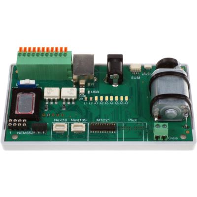
Test decoders and their outputs outside the locomotive.
View product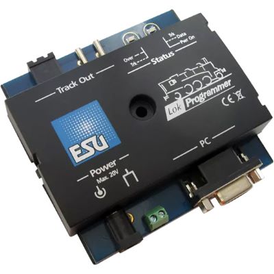
Edit the direction, mapping and motor parameters graphically.
View product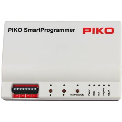
Configure SmartDecoder projects and test vehicles.
View product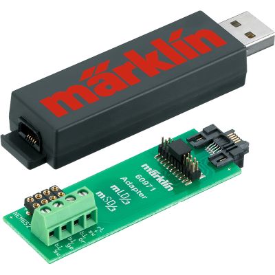
Edit mLD3 and mSD3 projects on a computer.
View product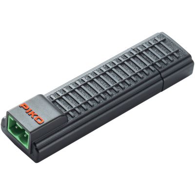
Compact programming interface for compatible XP decoders.
View product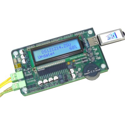
Read, write and update ZIMO decoders.
View product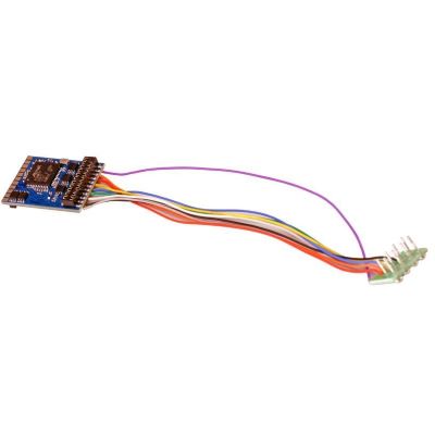
Multi-protocol decoder with an eight-pin connection.
View product
PluX22 decoder for modern H0 vehicles.
View product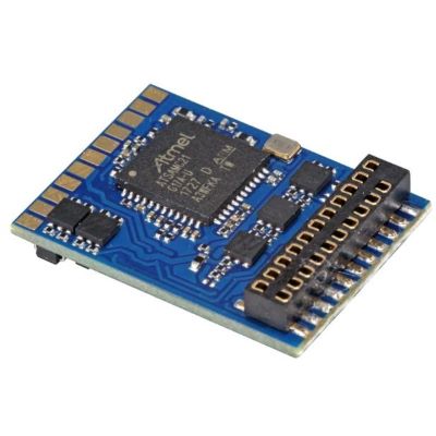
DCC decoder for 21MTC vehicle circuit boards.
View product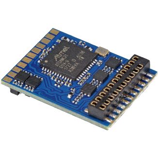
21MTC decoder supporting DCC, Motorola and M4.
View product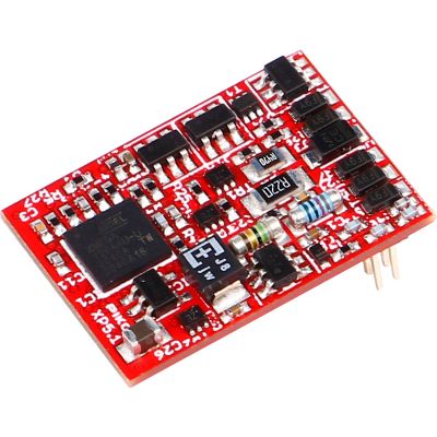
Multi-protocol decoder with a PluX22 interface.
View product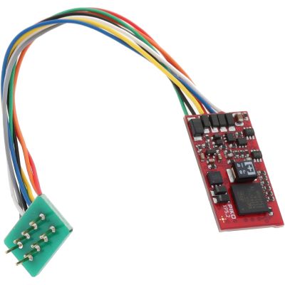
Eight-pin decoder supporting several digital protocols.
View product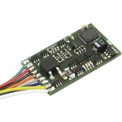
DCC decoder with an NEM 652 plug.
View product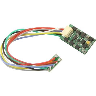
Multi-protocol decoder with a conventional plug.
View product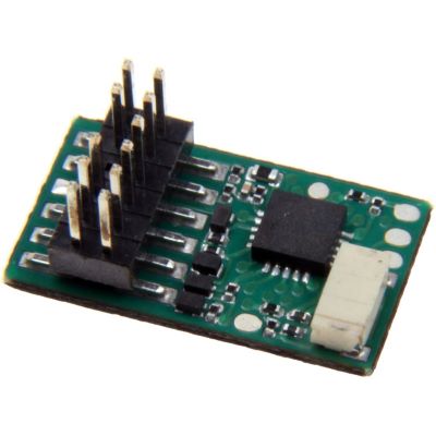
PluX12 version for suitably prepared TT models.
View product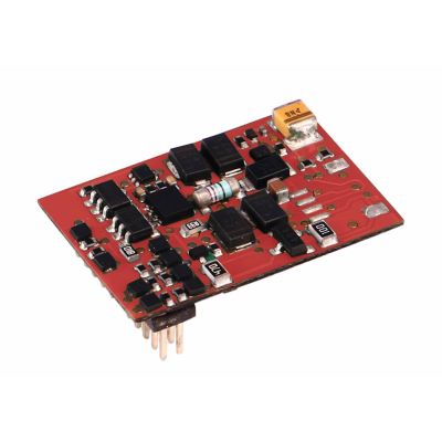
Compact multi-protocol decoder for TT gauge.
View product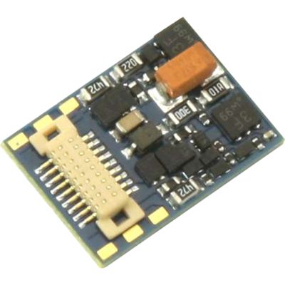
Micro decoder with a modern Next18 interface.
View product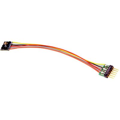
Six-pin decoder for small vehicles.
View product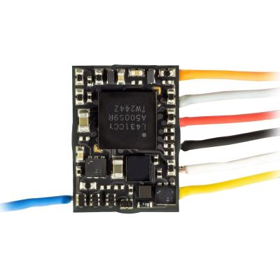
Very compact direct NEM 651 decoder.
View product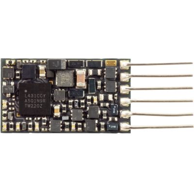
Low-profile direct decoder for small models.
View product
Wired decoder for small and narrow vehicles.
View product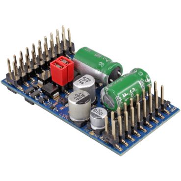
High-output decoder for large vehicles.
View product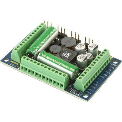
XL sound decoder with screw terminals.
View product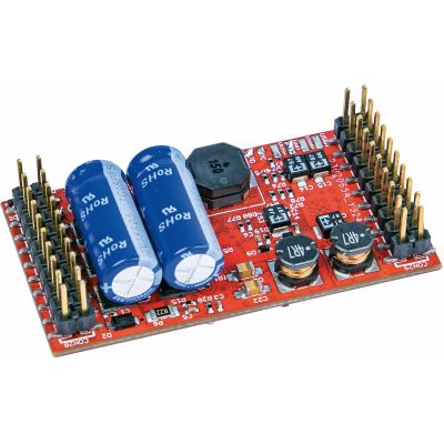
Blank sound decoder for garden-railway models.
View product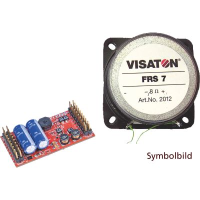
Large-scale sound decoder supplied with a loudspeaker.
View productBit 0 in CV 29 reverses the digital direction and direction-dependent lighting functions.
Add 1 when the current value is even, or subtract 1 when it is odd. Every other CV 29 setting remains unchanged.
Swap them when only the motor runs in the wrong direction while the direction-dependent lighting already matches the intended vehicle front.
No. The digital direction is determined by the DCC driving command. Red and black are the decoder's track connections.
CV 29 Bit 0 reverses the motor and lighting logic together. If only the motor wiring was wrong, correct the motor connection instead.
The direction entry in the command station or Bit 7 of the DCC consist address in CV 19 may reverse the locomotive within the consist.
Under the basic DCC definition, Bit 0 concerns digital operation. Check the analogue direction and manufacturer-specific settings separately.
Incorrect orientation may affect the motor and lighting functions. Compare the pin-1 markings on the decoder and socket with the power switched off.
Certain mLD3 and mSD3 decoders provide separate settings for motor and lighting inversion. Consult the CV table for the exact decoder family.
A normal DCC CV change does not require registration. An mfx locomotive record is normally retained, but registration should be checked after larger project changes.
Further decoder guides, interface comparisons and buying advice are available in the central model railway guide.