Amplified AUX
Contains its own output stage. LEDs, suitable lamps, relays, digital couplers and other loads may be connected directly only within the decoder manufacturer's permitted individual and total current limits.

Headlights, tail lights, cab lighting, engine-room lighting, high beam, shunting lights and interior lighting turn a digitised locomotive into a much more realistic model.
The order is crucial: first check the output type, permitted load and vehicle circuit board. Then connect the LED with suitable current limiting. Only afterwards should the AUX output, function button, direction, dimming and lighting effect be programmed.
In addition to its motor output, a vehicle decoder can provide several electrical connections for lighting and auxiliary functions. Conventional front and rear lighting outputs are often already configured for direction-dependent headlights. Additional connections can be called AUX1, AUX2, FA1, FA2, A1 or similar, depending on the manufacturer.
The electrical name alone does not tell you what may safely be connected. An amplified function output contains its own output stage and can directly switch a suitable load within the manufacturer's specified current limits. A logic-level output, by contrast, supplies only a control signal for a suitable vehicle circuit board, transistor stage or other compatible electronics.
The next step is function mapping . It determines which function button activates which output and under which operating conditions. F0 can therefore control the standard headlights, F1 the cab lighting, F6 a high-beam function and another button white shunting lights at both ends.
Output effects come afterwards. Many modern decoders can dim lighting, fade it in and out, flash it or simulate particular lamp effects. These functions are manufacturer-specific. Never copy a mapping or dimming CV from an unrelated decoder without checking the correct instructions.
The decoder output voltage, LED forward voltage and existing vehicle circuit must be known. Modern LEDs often need only a few milliamps for a convincing model-railway brightness. When in doubt, begin with a higher series resistance and lower brightness.
Contains its own output stage. LEDs, suitable lamps, relays, digital couplers and other loads may be connected directly only within the decoder manufacturer's permitted individual and total current limits.
Does not provide normal load current. It is intended, for example, to control a suitable vehicle circuit board or an additional transistor or amplifier stage.
Usually configured for direction-dependent headlights. Function mapping can nevertheless change the assignment, brightness and operating conditions.
SUSI is intended for communication with compatible auxiliary modules and can also provide module power where specified. Its contacts must not automatically be treated as normal load-bearing function outputs.
Pantographs, moving doors, smoke generators and digital couplers can require special signal forms, operating times or protective circuits.
Many wired decoders provide a separate common positive connection for function loads. Vehicle circuit boards can nevertheless use different internal arrangements, so the pin assignment must always be checked.
| Connection | Typical Application | Direct Load? | Check First |
|---|---|---|---|
| Amplified AUX | LED, lamp, relay, digital coupler | within the decoder limits | individual and total current |
| Logic-Level AUX | control input on a vehicle circuit board | no | signal level and amplifier stage |
| SUSI | sound and auxiliary modules | compatible module only | pin assignment and power supply |
| Servo | pantograph, doors, moving function | only as specified | signal, power supply and end positions |
| Loudspeaker | sound decoder | compatible loudspeaker only | impedance and power rating |
The calculator provides a technical reference value for one LED or several LEDs connected in series. The lighting planner then documents which AUX output should receive which function, direction condition and function button.
Output voltage minus the combined LED forward voltage gives the voltage that must be dropped across the resistor.
The next higher common E12 value is 2.7 kΩ.
The plan is stored only in the local browser and does not change any settings on the locomotive or decoder.
Test the electrical output first. Add mapping, dimming and special effects one at a time afterwards.
Direction-dependent white front lighting remains the basic function. Reduce the brightness so that individual LEDs do not resemble excessively bright modern car headlights.
Make red tail lights separately switchable so that they can be turned off when the locomotive is hauling a train.
Ideally illuminate only the active cab and preferably only while stationary or at very low speed.
Can be implemented as a second brightness level on the same output or with separate LEDs and an additional output.
Depending on the prototype, switch white lights at both ends or another appropriate shunting signal together with shunting mode.
Subtle internal lighting can add convincing depth to modern electric locomotives and large diesel locomotives.
Function decoders are especially useful for control cars, multiple units and coaches whose lighting should be operated independently of the locomotive.
This is not a normal lighting load. Output capacity, pulse duration and protective functions must explicitly match the coupler being used.
Record the family, product number, interface and firmware.
Identify existing resistors, transistor stages and pin assignments.
Clearly distinguish amplified AUX outputs from logic-level outputs.
Compare the load current with the individual and total decoder limits.
Check polarity and provide suitable current limiting.
Connect and test only one new lighting function at a time.
Assign the function button, direction and any additional conditions.
Begin with a low brightness setting and adjust it visually.
Add high beam, fading, flashing or a timed function only afterwards.
Document function buttons, AUX assignments and the completed decoder project.
Output names, mapping tables, electrical limits and programming procedures differ between decoder families. Always check the exact decoder installed in the vehicle.
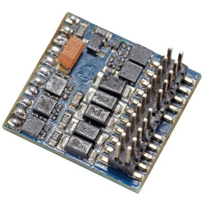
PluX22 function decoder with ten amplified function outputs and two additional logic-level outputs for extensive lighting and auxiliary functions.
View Product →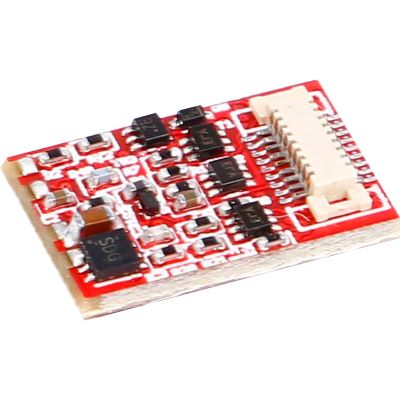
Function decoder with ten function outputs, including six load-bearing outputs and four logic-level outputs, plus flexible mapping up to F68.
View Product →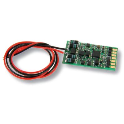
Six outputs with switching, dimming, flashing, fade-in and fade-out functions for coaches and functional models.
View Product →
Locomotive decoder for vehicles requiring extensive lighting, mapping and additional function control.
View Product →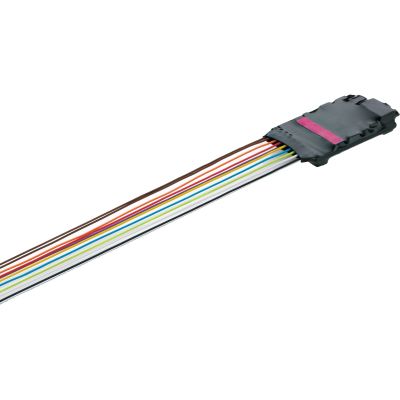
Multi-protocol retrofit decoder with numerous digitally switchable functions for suitable Märklin, Trix and other H0 conversions.
View Product →| Gauge | Typical Interfaces | Lighting Consideration |
|---|---|---|
| Z | direct wiring / specialist circuit board | minimal installation space and very small LEDs |
| N | Next18, NEM 651 | logic-level outputs on vehicle circuit boards are often particularly relevant |
| TT / TTe | Next18, PluX12, PluX16 | compact function mapping with limited installation space |
| H0 / H0e / H0m | PluX22, 21MTC, Next18, NEM 652 | widest range of separately controllable lighting and AUX functions |
| 0 | circuit board, wires, screw terminals | cab, engine-room lighting and digital couplers are often controlled separately |
| 1 / G | large-scale decoder / screw terminals | higher load currents and numerous auxiliary functions |
Check polarity, series resistor, output type, common return, function mapping and the vehicle circuit board. A logic-level output cannot power an LED like an amplified AUX output.
Check the current limiting immediately. Decoder dimming does not replace an electrically required series resistor.
Check for trapped wires, a short circuit against the chassis or unwanted mechanical contact with the body shell.
Check the direction condition in the function mapping before rewiring the vehicle.
On compatible decoders, add a stationary or speed condition to the function mapping.
Switch off track power immediately and check output currents, wiring and possible short circuits. Do not continue testing with higher dimming values.
The product search reads current English decoder, command-station and manufacturer pages. Every discovered product detail page is checked before display. Products with a recognised archive notice are excluded, smaller product images are normalised to the 400-pixel shop version and delivery or stock information is deliberately not displayed on the cards.
Live checking will begin when you approach this section.
Once all lighting outputs work correctly electrically, configure the function buttons, directions and operating conditions. Only then add dimming, fade-in and fade-out times and special effects. This makes it much easier to determine whether a fault is electrical or purely a programming issue.
With interfaces such as Next18, 21MTC and PluX, individual connections can be amplified, switched or used for specialist functions by the vehicle circuit board. Always consider the decoder documentation and vehicle documentation together.
AUX describes an additional function output on a vehicle decoder. Suitable outputs can switch cab lighting, tail lights, interior lighting, digital couplers or other compatible loads.
An amplified AUX contains an output stage and can switch a suitable load within its specified current limits. A logic-level output supplies only a control signal for compatible electronics.
Only when suitable current limiting is already present. If the vehicle circuit board does not contain an appropriate resistor or current-limiting circuit, the LED must be connected with suitable electrical protection.
Many modern decoders allow function outputs to be dimmed using PWM. Programmed dimming does not replace an electrically required series resistor.
Function mapping assigns function buttons to physical decoder outputs and, on advanced decoders, to operating conditions such as direction, stationary operation or other logical functions.
Yes, provided that the vehicle circuit board and decoder provide separate or independently controllable lighting circuits.
Ideally, both cabs are controlled separately. Suitable decoders can additionally use the direction of travel and stationary operation as mapping conditions.
Advanced mapping systems can allow complex assignments and several triggers. The available combinations depend on the exact decoder family.
On some decoder and interface variants, particular AUX connections are implemented as logic-level outputs. A suitable amplifier stage is then required before connecting a normal electrical load.
The permitted current is decoder-specific. Both the maximum load of each individual output and the decoder's total function-output load must be observed.
Possible causes include a short circuit, overload or an electrically incorrect connection. Switch off track power immediately and check the wiring and output loads.
A function decoder without a regulated motor output is often ideal. The number and type of outputs, interface, current capacity and digital protocol must suit the vehicle.
The comprehensive Model Railway Guide covers decoders, function mapping, digital command stations, interfaces, motor control, sound, electrical systems and many other topics.