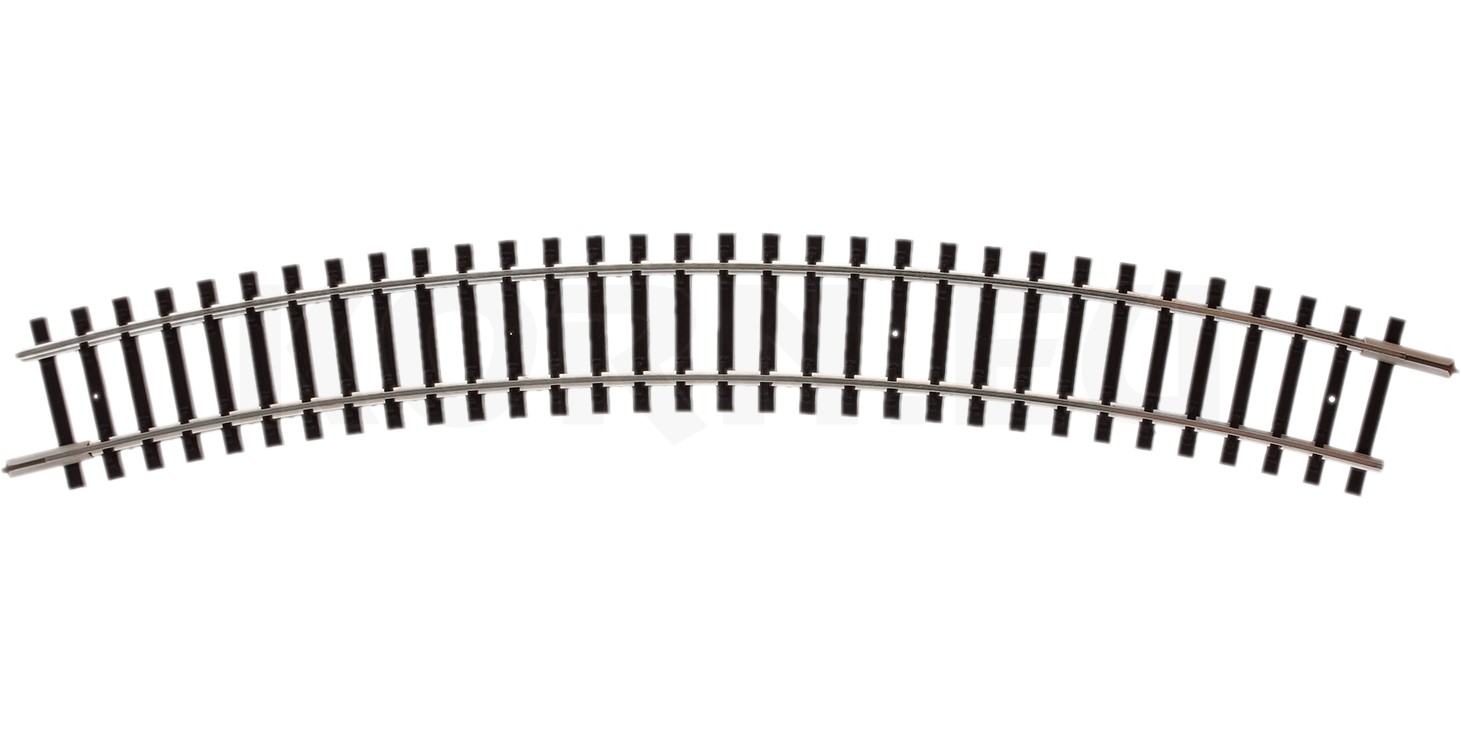
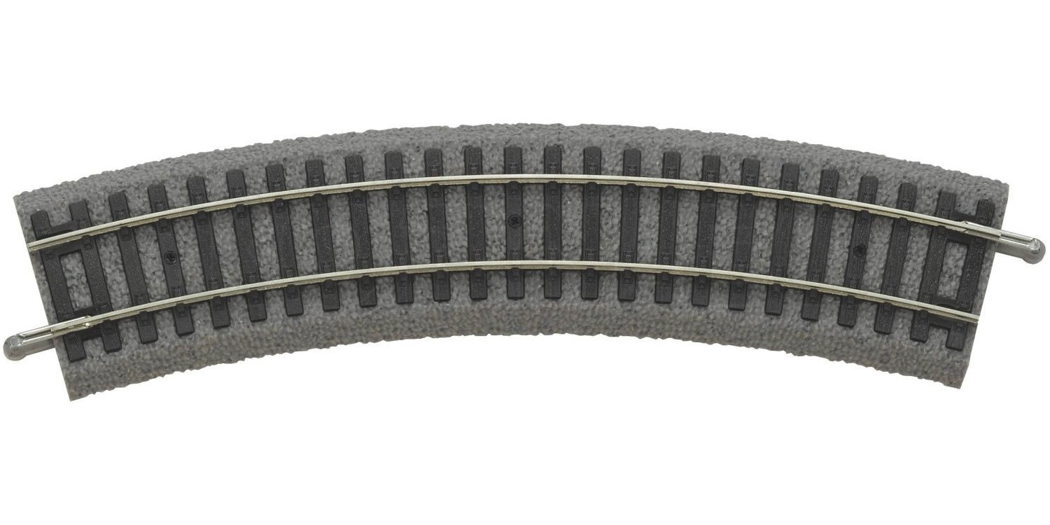
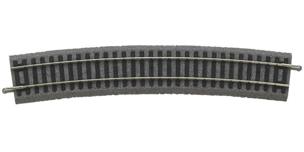
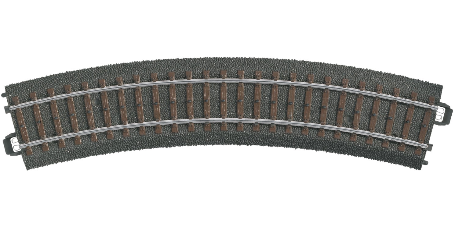
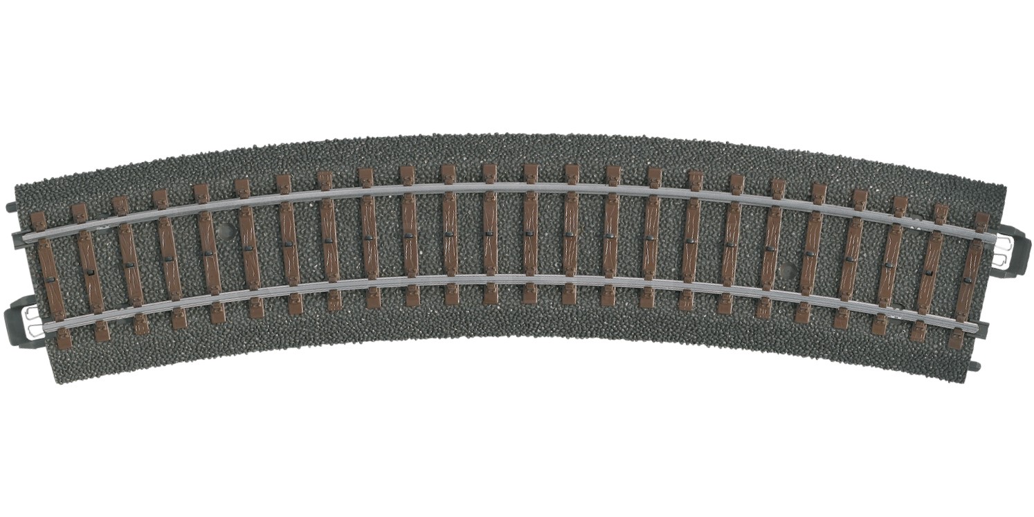
The sections between the curves
Turn a circle into a reliable route
Check overhang and parallel tracks together
A vehicle may negotiate a curve on its own yet still collide with an oncoming train.
NEM 112, 2024 edition
, covers track spacing according to inner radius and rolling stock group. The increased spacing must already be in place at the beginning of the curve.
NEM 103
adds the required clearance on curves.
Move two long vehicles slowly past each other. Check the vehicle ends, steps, loads and couplings as well. Only then should platforms, bridge sides or tunnel portals be fixed permanently. General standard tables may be insufficient for unusually wide models.
Ease reverse curves and transitions
When a left-hand curve changes directly into a right-hand curve, adjacent vehicle ends move sharply relative to each other. A suitable intermediate straight or a properly formed transition curve eases this section. Its length depends on the rolling stock and coupling type; an arbitrary short straight is not a universal solution.
NEM 113
describes transition curves with a continuously changing radius. With flexible track, take particular care to avoid kinks at the rail joiners. Curved turnouts must also be included: the system name printed on them does not replace checking the actual running radii and connecting track geometry.
Gradients and tight radii increase the demands
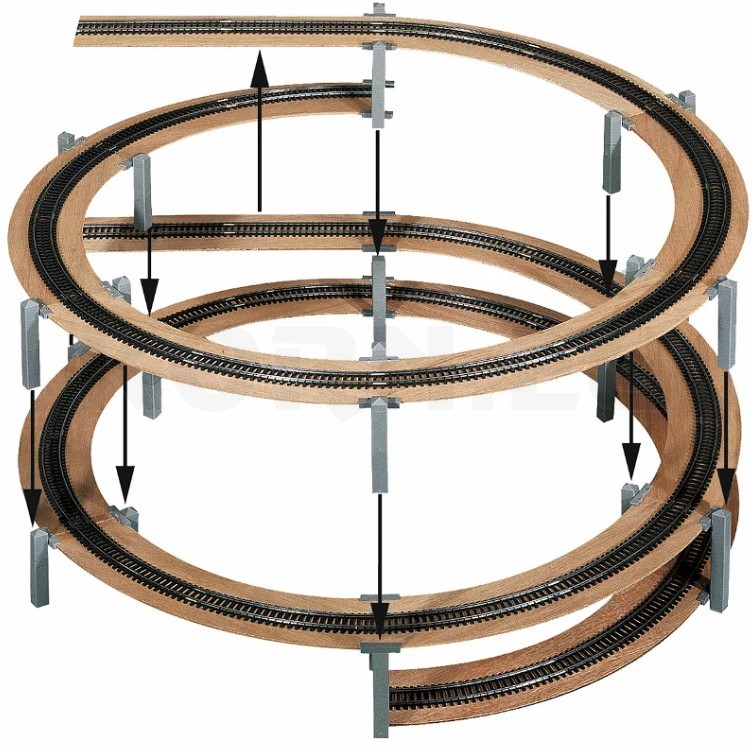
In a
Track helix
continuous curved running combines with a gradient. For a rise of 90 mm per turn, a 360 mm radius gives a calculated gradient of approximately 3.98%; a 600 mm radius gives approximately 2.39%. These are calculation examples, not operational limits.
Tractive effort also depends on locomotive weight, traction tyres, rolling resistance and train length. A larger radius can reduce the gradient and make curves easier to negotiate at the same time. Test the actual train when starting on the curve; a locomotive already in motion may pass a section where it cannot restart with its train.
Practical project: build an H0 test curve
For a meaningful test, you need the intended track, a level base, a tape measure, a set square, connection materials and your most demanding models. Begin with an easily accessible setup. Fix flexible track temporarily and check the track centreline dimensions along the entire curve.
1. Record the geometry
Note the radius, track components, couplings and fitted detail parts. Mark the transition to the straight and the planned spacing to the adjacent track. Compare the dimensions with every relevant model’s instructions.
2. Run the most demanding combination
Test long coaches or wagons, the largest locomotive and mixed vehicle lengths slowly forwards and backwards. Add the planned turnout and, where relevant, a gradient. Watch for wheels lifting and couplings binding sideways.
Especially when propelling trains
Pushing forces can cause different problems from pulling forces. Test push-pull trains and longer groups of vehicles during shunting as well.
A clear reason to stop
If a wheel lifts or a coupling pushes a vehicle sideways off the track, change the geometry. Increasing speed does not fix the problem.
3. Recreate the complete installation
Position obstacles temporarily at first. Check passing movements and access for maintenance. Only when the final operating arrangement works reliably should you proceed with permanent gluing, ballast and scenery.
When derailments occur despite a suitable radius
Start where the first wheel begins to climb the rail. Check for kinks, changes in rail height, a twisted trackbed and foreign objects. Then check freely moving bogies, close-coupling mechanisms and correctly fitted detail parts. If the fault affects only one vehicle, compare its wheelsets and assembly with the instructions. If the cause remains unclear, an easily accessible test circle helps narrow it down.