
NEM 652: Understanding the 8-Pin Decoder Interface
What do the eight contacts mean, where is pin 1 and which locomotive, function or sound decoder suits your vehicle? This guide explains the pin assignment, installation, digital protocols, gauges, advantages and limitations of the classic NEM 652 interface.
8 Contacts
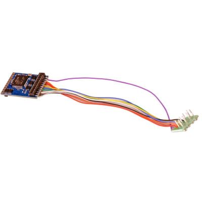
Classic H0 interface according to MOROP
What Is an NEM 652 Interface?
NEM 652 describes a standardised eight-pin electrical connection between a model locomotive and a digital decoder. The socket is located in the vehicle. The decoder has a matching eight-pin plug, which is usually connected to the decoder board by a short wiring harness.
The interface connects the track voltage, motor, front and rear lighting and common positive conductor. One additional contact may remain unused or may be employed by the vehicle manufacturer for a documented auxiliary function. NEM 652 therefore provides more options than the six-pin NEM 651 interface , while remaining simpler than Next18, PluX22 or 21MTC.
The connection is particularly common in H0 locomotives from earlier generations of digital technology and in vehicle designs that continue to use a flexible wired plug. Numerous older analogue models already have a factory-fitted interface with a blanking plug and can therefore be digitised without completely rewiring the vehicle.
NEM 652 does not define the digital protocol. A decoder may support DCC, Motorola, Selectrix, an mfx-compatible format or several protocols. The command station, motor load and required functions must therefore also be checked.





Pin 1 to pin 8
How Is the Eight-Pin NEM 652 Plug Assigned?
The contacts are arranged in two rows. A marking on the plug, an orange wire or a dot on the circuit board normally identifies pin 1. The vehicle instructions remain decisive when determining the orientation.
| Contact | Function | Wire Colour | Practical Meaning |
|---|---|---|---|
| 1 | Motor Connection 1, Positive | Orange | First motor terminal, isolated from the track pickups |
| 2 | Rear Light, Negative | Yellow | Switched output for the rear light |
| 3 | No Fixed Assignment | Green, If Used | May be used for a documented auxiliary function |
| 4 | Left-Hand Track Pickup | Black | Connection to the left-hand rail |
| 5 | Motor Connection 2, Negative | Grey | Second motor terminal, isolated from the track pickups |
| 6 | Front Light, Negative | White | Switched output for the front headlight |
| 7 | Common Conductor, Positive | Blue | Common positive conductor for lighting and functions |
| 8 | Right-Hand Track Pickup | Red | Connection to the right-hand rail |
Special Feature of Contact 3
A Green Wire Is Not Automatically Present
Contact 3 is unassigned in the basic configuration. When a manufacturer uses it for an auxiliary function, the alternative assignment must be documented and protected against possible reverse insertion. A decoder must therefore not be selected solely by the visible plug shape.
Dimensions and current capacity
Which Technical Data Does NEM 652 Define?
The standard sheet defines not only the contact assignment, but also the spacing, pin dimensions and recommended installation space. The permitted ratings of a particular decoder may nevertheless be lower.
How Large Must the Installation Space Be?
The standard recommends at least 31 × 18 × 7 millimetres for a standard decoder. For a sound decoder, at least 38 × 18 × 7 millimetres is specified. Additional space is required for the plug, cable bend and, on sound conversions, the loudspeaker and sound enclosure.
Modern decoders may be considerably smaller. This does not automatically mean that they are electrically compatible with every locomotive. The motor current, heat generation, lighting current, function outputs and vehicle-specific circuitry remain decisive.
The current capacity of the interface contacts must not be confused with the decoder's output rating. A decoder may, for example, be rated for a motor current of 0.7 or 0.9 A even though the standard contacts can fundamentally carry higher currents.
From Z gauge to garden railways
Which Gauges Use NEM 652?
The interface is not restricted to a particular nominal scale. Its main area of application is H0. Compact micro decoders also permit its use in individual N-, TT- and narrow-gauge vehicles.
| Gauge | Typical Use | Classification | Common Alternatives |
|---|---|---|---|
| Gauge Z | Only in exceptionally spacious vehicles using micro decoders. | Very Rare | Permanently wired nano decoders |
| Gauge N | Individual vehicles with an eight-pin socket or function decoder. | Occasional | NEM 651, Next18 and E24 |
| Gauge TT | Older or spacious locomotives and specialist conversions. | Possible | NEM 651, Next18 and PluX16 |
| Gauge H0 | Locomotive, function and sound decoders in many older vehicles. | Main Application | PluX22, 21MTC, Next18 and NEM 652 |
| H0e and H0m | Larger narrow-gauge vehicles with sufficient space. | Sometimes | NEM 651, Next18 or wired decoders |
| Gauge 0 | Smaller motors and prepared vehicle circuit boards. | Possible | More powerful Gauge 0 decoders |
| Gauges 1 and G | Usually insufficiently rated for typical large-scale motors. | Hardly Common | Large-scale and high-current decoders |
Distinguishing interfaces safely
NEM 652 Compared with NEM 651, Next18, PluX and 21MTC
The socket fitted to the vehicle determines the plug shape. A different interface can be used only with a suitable adapter board or professional rewiring.
| Interface | Design | Typical Gauges | Range of Functions | Special Feature |
|---|---|---|---|---|
| NEM 651 | Six pins in one row | N, TT and narrow gauge | Motor and two lighting outputs | Very compact, without a common positive contact |
| NEM 652 | Eight-pin plug with a wiring harness | Mainly H0 | Motor, lighting and common positive conductor | The decoder can be positioned flexibly |
| Next18 | Flat plug-in connection with 18 contacts | N, TT and compact H0 | Several auxiliary functions and sound | Considerably more compact than NEM 652 |
| PluX16 / PluX22 | Two-row pin header on the decoder | TT and H0 | Numerous amplified function outputs | Reverse-polarity protection through a missing contact |
| 21MTC | Decoder socket fitted to vehicle-side pins | Mainly H0 | Numerous functions and sound | Check the standard and MKL versions |
A detailed comparison is available in the decoder interface comparison .
Digitisation without unnecessary risk
Install and Test an NEM 652 Decoder Correctly
Work only on a vehicle that is completely disconnected from the power supply. Open the body according to the manufacturer's instructions and retain the existing blanking plug carefully.
Check the Interface
Confirm that the vehicle actually has an eight-pin NEM 652 socket.
Determine the Motor Current
The decoder's continuous and peak ratings must suit the motor.
Open the Body
Expose screws, retaining clips, lighting and wires carefully.
Remove the Blanking Plug
Pull the analogue plug straight out of the socket and store it safely.
Find Pin 1
Compare the markings on the vehicle board and plug with the orange wire.
Insert the Plug
Guide all eight pins evenly into the socket without using force.
Route the Wires
The wires must not touch the flywheel, gearbox or other moving components.
Insulate the Decoder
Prevent contact with the metal chassis and exposed circuit-board tracks.
Use the Programming Track
Read the decoder first so that connection faults can be detected early.
Test the Motor
Check slow-speed operation, direction, noise and decoder temperature.
Check the Lights
The front and rear lights must match the selected direction of travel.
Close the Body
Reassemble all components without mechanical stress only after a successful test.
Plug Accidentally Reversed
Switch Off the Track Voltage Immediately If the Vehicle Behaves Unusually
The plug is not completely protected mechanically against incorrect orientation. If the locomotive does not move, the lighting functions react incorrectly or the decoder becomes hot, check pin 1, contact 3, motor isolation and the vehicle circuitry again.
Locomotive, function or sound decoder
Which NEM 652 Decoder Fits My Vehicle?
The Eight-Pin Plug Is Only the First Selection Criterion
A locomotive decoder controls the motor, lighting and auxiliary functions. A function decoder has no motor output and is suitable for control cars, illuminated coaches or function models. A sound decoder combines motor control and functions with digitally stored vehicle sounds.
The motor current, motor control, digital protocol, dimensions and function outputs are decisive when choosing a locomotive decoder. A multiprotocol decoder is suitable for changing system environments. A DCC-only decoder may be appropriate when the entire layout is operated consistently with DCC .
Sound decoders additionally require a suitable sound project, loudspeaker, impedance, sound enclosure and vehicle assignment. Products prepared for a specific locomotive class should be used only in the models expressly stated.
Additional functions may be available through separate wires or solder pads. These connections are not automatically part of the standard eight-pin assignment. The decoder instructions specify which loads may be connected.
Selection by gauge and application
NEM 652 Decoders for H0, N, TT and Function Models
On each product page, also check the dimensions, motor current, protocols, function outputs, sound project and vehicle assignment. The gauge designation alone does not replace a technical compatibility check.
Main Application: Gauge H0
8-Pin Locomotive Decoders Without Sound
These decoders are suitable for classic H0 locomotives with an eight-pin socket. They differ in their protocols, motor-current capacity, RailCom support, braking functions and function mapping.
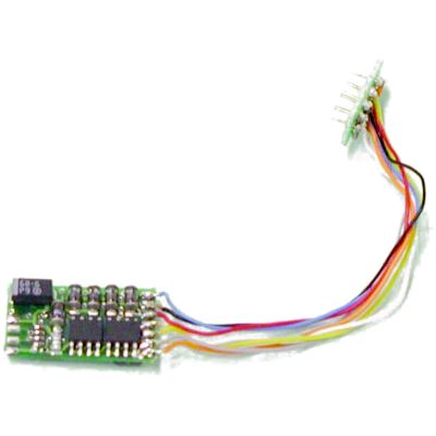
H0 Multiprotocol
PIKO 56122 Hobby Decoder
Straightforward DCC and Motorola decoder for classic H0 digitisation projects.
View Product
H0 Multiprotocol
ESU 59610 LokPilot 5
Versatile locomotive decoder supporting DCC, Motorola, Selectrix and M4.
View Product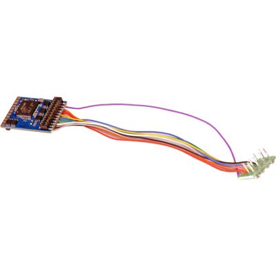
H0 DCC
ESU 59620 LokPilot 5 DCC
DCC-only locomotive decoder for precise motor and lighting control.
View Product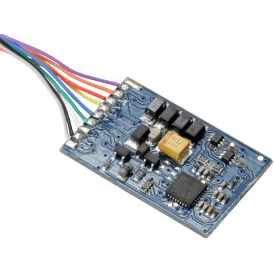
H0 DCC Basic
ESU 59020 LokPilot 5 Basic
DCC decoder with RailComPlus and automatic motor adjustment.
View Product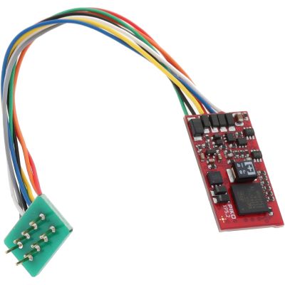
H0 mfx-Compatible
PIKO 56503 SmartDecoder XP 5.1
Multiprotocol decoder supporting DCC, Motorola, RailCom and mfx functionality.
View Product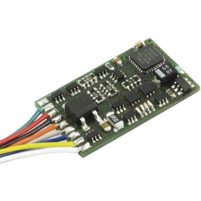
H0 DCC
Lenz 10231-02 Standard+
DCC locomotive decoder with three protected function outputs.
View Product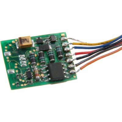
H0 RailComPlus
Uhlenbrock 74320 ID2
IntelliDrive 2 decoder with feedback and modern motor control.
View Product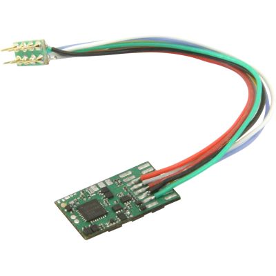
H0 Multi-Format
Uhlenbrock 74120 ID2
Compact multi-format decoder for several digital systems.
View ProductSmall Vehicles in N, TT and H0
Micro and Function Decoders with NEM 652
Small decoder boards permit the use of the eight-pin plug in selected N- and TT-gauge vehicles. Function decoders are intended for control cars and models without a motor.
N, TT and Z
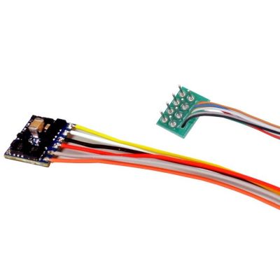
ESU 59810 LokPilot 5 micro
Compact multiprotocol decoder for restricted installation spaces.
View Product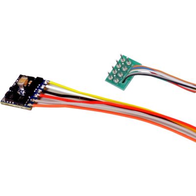
N and TT DCC
ESU 59820 LokPilot 5 micro
Very small DCC locomotive decoder for compact vehicles.
View Product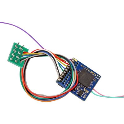
H0 Function
ESU 59210 LokPilot 5 Fx
Multiprotocol function decoder for control cars and illuminated models.
View Product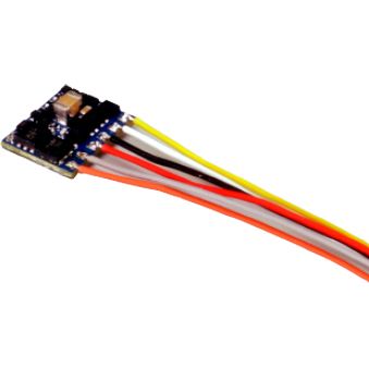
N and TT Function
ESU 59120 LokPilot 5 Fx micro
Compact DCC function decoder for lighting and auxiliary functions.
View ProductSound Conversions for Gauge H0
NEM 652 Sound Decoders and Vehicle-Specific Projects
Universal blank decoders can be loaded with a suitable sound project. Vehicle-specific decoders are matched to particular locomotives or multiple units and should be used only as stated in the product description.
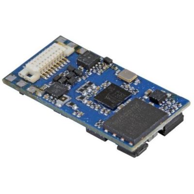
H0 Micro Sound
ESU 58810 LokSound 5 micro
Compact multiprotocol sound decoder for restricted installation spaces.
View Product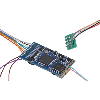
H0 Sound Project
ESU 58410 LokSound 5
Universal blank decoder for individually loaded sound projects.
View Product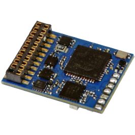
H0 Function Sound
ESU 58210 LokSound 5 Fx
Sound and function decoder for vehicles without their own traction motor.
View Product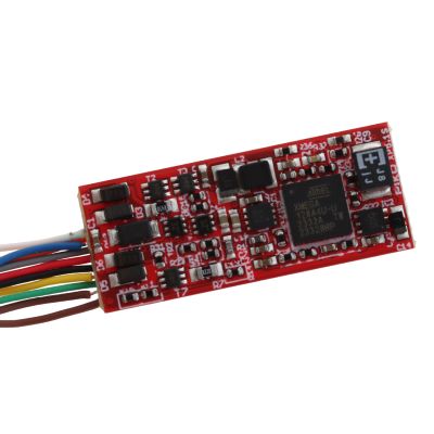
H0 Blank Sound
PIKO 56507 PSD XP 5.1 S
Blank sound decoder for individual PIKO sound projects.
View Product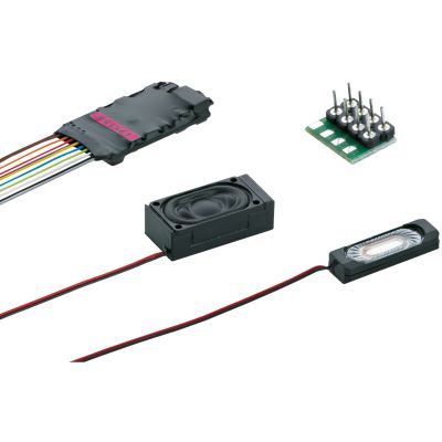
H0 Diesel Sound
Märklin 60986 mSD3
Retrofitting sound decoder with a prepared diesel-locomotive sound project.
View Product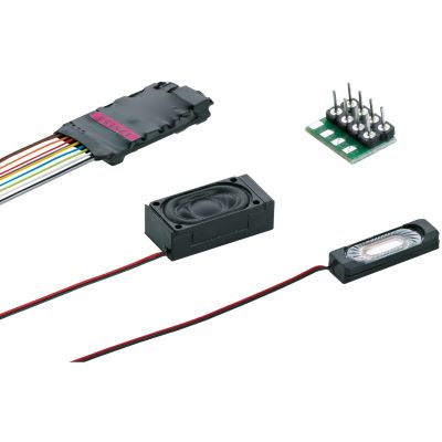
H0 Electric Sound
Märklin 60987 mSD3
Retrofitting sound decoder with a prepared electric-locomotive sound project.
View Product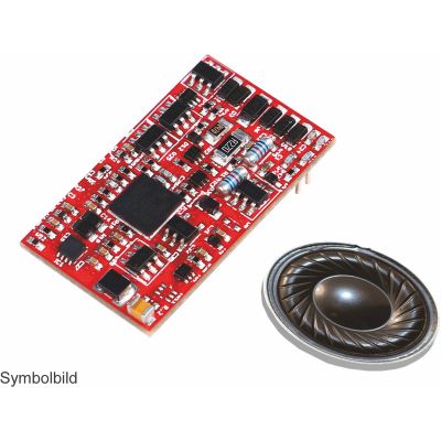
H0 Electric GTW
PIKO 56617 SmartDecoder
Vehicle-specific sound decoder for electric GTW multiple units.
View Product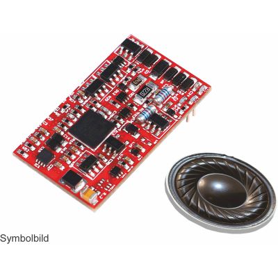
H0 Class 612
PIKO 56619 SmartDecoder
Sound decoder with a loudspeaker for suitable Class 612 multiple units.
View Product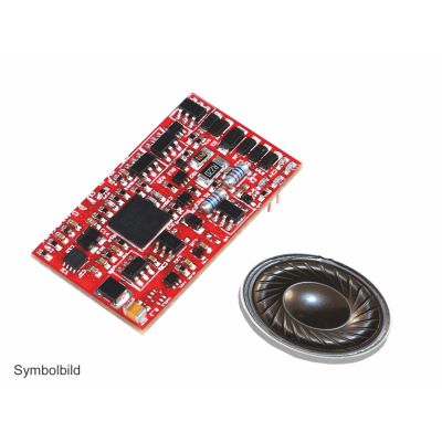
H0 G 1206
PIKO 56555 SmartDecoder
Vehicle-specific sound solution for suitable G 1206 diesel locomotives.
View ProductWorkshop and Decoder Testing for All Gauges
Test, Read and Program NEM 652 Decoders
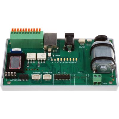
A decoder tester permits function checks outside the locomotive. This makes it easier to distinguish faults in the decoder, vehicle circuit board and wiring.
All Gauges
Uhlenbrock 71000 DigiTest
Testing and programming device for NEM 652, Next18, PluX and 21MTC.
View Product
Answers before purchase and installation
Frequently Asked Questions about the NEM 652 Interface
The vehicle and decoder instructions remain binding when making the final selection. The following answers provide general technical guidance.
What Does NEM 652 Mean on a Model Locomotive?
The vehicle has a standardised eight-pin socket for a suitable digital decoder. The motor, track power and lighting are connected through the plug.
Is NEM 652 Automatically a DCC Connection?
No. The standard describes the electrical connection. The decoder may support DCC, Motorola, Selectrix, mfx-compatible formats or several protocols.
How Do I Identify Pin 1 on the Eight-Pin Plug?
Pin 1 is frequently identified by a dot, triangle, number or the orange motor wire. The vehicle instructions should also be consulted.
Can the NEM 652 Plug Be Inserted the Wrong Way Round?
Yes. The design is not completely mechanically keyed. The orientation must therefore be determined clearly before insertion.
What Happens If the Plug Is Reversed?
The motor, track-pickup and lighting connections are then assigned to different positions. The vehicle may not respond or functions may operate incorrectly. Vehicle-specific assignments may also cause damage.
What Is the Blue Wire Used For?
The blue wire is the common positive conductor for lighting and suitable auxiliary functions. The white, yellow or other function outputs switch the respective load side.
What Is Contact 3 Used For?
Contact 3 has no general basic function. It may remain unused or may be employed by the manufacturer for a documented auxiliary function.
Can an Analogue NEM 652 Locomotive Be Digitised?
Yes. The existing blanking plug is normally removed and replaced with a technically suitable decoder.
Is Sound Possible with NEM 652?
Yes. The sound decoder is connected through the eight-pin plug. The loudspeaker and possible auxiliary connections are connected separately to the decoder.
Does Every Eight-Pin Decoder Fit Every NEM 652 Locomotive?
No. The motor current, decoder dimensions, digital protocol, contact 3 assignment, function outputs and sound equipment must also be suitable.
Can NEM 652 Be Used in H0 AC and H0 DC?
The interface is found mainly in two-rail vehicles, but it can also be used in suitable centre-contact conversions. The decoder, motor and digital command station must be compatible.
Can I Replace NEM 652 with Next18 or PluX?
Not directly. The plug shape and contact assignment differ. Conversion requires a suitable adapter board or professional rewiring.
Reliable digital operation
Program and Protect NEM 652 Decoders over the Long Term
After installation, the locomotive address, acceleration and braking delay, maximum speed, lighting outputs and other functions can be programmed. Changes should be made gradually so that unwanted behaviour can be attributed clearly to a particular setting.
Clean track, maintained current pickups and a freely moving gearbox reduce current peaks. A stiff-running locomotive may overload the decoder even if it appeared to operate adequately in analogue mode.
Further introductory information is available in the guides to Digital Model Railway Basics , Locomotive Decoders and Digital Modules and Digital Protocols Compared .
More Knowledge about Decoders, Digital Technology and Model Railways
Discover further guides covering interfaces, digital command stations, protocols, gauges, layout planning, vehicles and technical model railway accessories.