



Basic Understanding
Change from Analogue to Digital
First learn how the command station, address, decoder and track signal work together and which parts of an analogue layout can remain in use.
Understand Digital Model Railways →
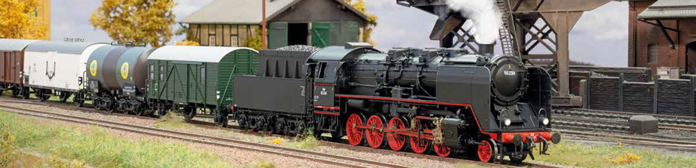
How does a driving command travel from the handheld controller to the locomotive? What is the difference between locomotive decoders, function decoders, feedback modules and boosters? This overview guides you step by step through the most important digital model railway terms.
On a digital model railway, the track carries a coded control signal. The digital command station generates this signal from inputs made using a handheld controller, touchscreen, smartphone or computer. Every digital locomotive contains a decoder with its own address and responds only to commands intended for it.
Several locomotives can therefore operate independently on the same electrically powered track. Speed, direction, lighting, sound, couplers and other functions are controlled using digital commands. Traction power and control information are transmitted together through the track.
The command station alone does not create a fully automated layout. Accessory decoders operate turnouts and signals. Feedback modules detect occupied tracks or triggered contacts. Boosters supply additional power districts. Digital buses connect controllers, feedback modules and other system devices.
Digital protocols determine how commands are encoded. DCC, mfx and Motorola are particularly widespread. Selectrix remains in use on existing and specialist layouts. RailCom adds a feedback channel from the decoder to compatible DCC control equipment.
Wi-Fi and LAN, by contrast, concern the connection between the digital command station, handheld controller, smartphone, tablet or computer. They do not replace the track protocol. A Wi-Fi command station can be operated through an app while still transmitting DCC to the track.
First learn how the command station, address, decoder and track signal work together and which parts of an analogue layout can remain in use.
Understand Digital Model Railways →This path explains locomotive decoders, function decoders, accessory decoders, feedback, boosters and digital buses using practical examples.
Discover the Components →Learn why the decoder and command station must support at least one common digital protocol.
Compare Protocols →Learn the difference between the network connection, user interface, app, router and track signal.
Understand Mobile Control →Begin with the general operating principle or open the explanation of the component or digital protocol you are looking for directly.
Addresses, driving commands, decoders, multiple-train operation and the difference between analogue and digital operation.
Generating the track signal, managing locomotives, programming tracks, accessory control and connections to controllers and modules.
Installation position, motor control, locomotive address, lighting functions, interfaces and selection by motor current and vehicle size.
Digital interior lighting, tail lights, couplers and special functions in driving trailers, passenger coaches and functional models.
Control turnouts, signals, uncouplers, servos and lighting using digital accessory addresses.
Detect track occupancy, contacts and sensors and report them to the command station or model railway software.
Provide additional power and divide the layout into separate power and short-circuit districts.
LocoNet, XpressNet, s88N, R-Bus, CAN and ECoSlink connect controllers, feedback modules, boosters and other devices.
Compare DCC, mfx, Motorola and Selectrix by addresses, registration, feedback and typical system environments.
Addresses, speed steps, CV programming, accessory commands, multiple-unit operation and cross-manufacturer use.
Locomotive registration, function symbols, mfx+, the Märklin system and differences from DCC and Motorola.
Addressing, older Märklin decoders, solenoid accessories and use with modern multiprotocol command stations.
Selectrix vehicles, the system bus, address space and the protocol’s importance for older N and multiprotocol layouts.
Return decoder information, detect locomotive addresses and understand the RailCom cutout and suitable detectors.
Distinguish between routers, access points, network cables, IP addresses, range and stable connections to the command station.
Combine apps, virtual throttles, track diagrams, Wi-Fi handheld controllers and computer programs effectively.
| Component | Typical Installation Location | Main Purpose | Most Important Selection Criterion | Read More |
|---|---|---|---|---|
| Digital Command Station | Operating position or technical area | Generate commands and manage the system | Protocols, output, buses and operation | Command Station |
| Locomotive Decoder | Locomotive or railcar | Control the motor and vehicle functions | Interface, dimensions and motor current | Locomotive Decoder |
| Function Decoder | Coach or functional model | Switch lighting and auxiliary functions | Outputs, voltage and interface | Function Decoder |
| Accessory Decoder | Under or beside the layout | Operate turnouts, signals and accessories | Pulse, continuous current, servo or relay | Accessory Decoder |
| Feedback Module | At track sections and contacts | Report states back to the control system | Detection method and feedback bus | Feedback |
| Booster | Between the command station and track district | Amplify the digital track signal | Booster bus, voltage and output current | Booster |
| Digital Bus | Between system devices | Transmit commands and feedback | Protocol and electrical pin assignment | Digital Bus |
A handheld controller, touchscreen, smartphone or computer generates the required driving or switching command.
The command station converts the input into a digital protocol supported by the decoder.
The power stage provides voltage and current for the respective track district.
The locomotive or accessory decoder recognises its address and executes the received command.
A current detector, contact or sensor recognises a state on the model railway layout.
The report travels through the appropriate bus to the command station or control software.
Small vehicles require particularly compact decoders. Installation space, component height, motor current and a low track voltage are more important than the highest possible booster output.
Next18, NEM 651, PluX12 and PluX16.
H0 offers the widest selection of locomotive, sound and function decoders. Centre-stud and two-rail systems affect the vehicle version and feedback technology.
PluX22, 21MTC, NEM 652, Next18 and specialist circuit boards.
Powerful motors, sound, lighting and smoke generators require high-capacity decoders, heavier wiring and clearly separated power districts.
Wires, screw terminals, large-scale interfaces and system circuit boards.
Record whether the layout uses two-rail or centre-stud track and note the gauge.
Note DCC, mfx, Motorola and Selectrix in the existing vehicle fleet.
Never choose a decoder solely by the number of pins or a product photograph.
Consider the motor, sound, lighting, smoke and accessories realistically.
Select feedback modules, controllers and interfaces that suit the command station.
Test a locomotive, turnout and detection section before completing the full expansion.
The decoder and command station must support at least one common protocol.
Without a regulated motor output, it cannot control a powered locomotive.
Solenoid mechanisms, motors, servos and lighting require different outputs.
Current detectors and common-ground contacts require different wiring.
Incorrect connections cause short circuits and equalising currents.
s88N, LocoNet and other buses are not ordinary LAN connections.
This selection contains 26 products for different gauges and tasks. The interface, voltage, current capacity, protocol and system bus must be checked before purchasing.
Small designs for restricted installation spaces, low motor currents and compact interfaces.
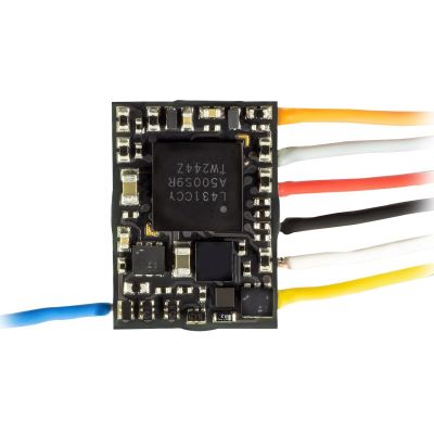
Compact driving decoder for very small installation spaces.
View Product →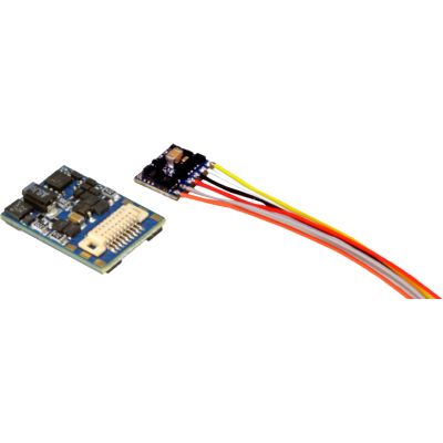
Compact locomotive decoder for suitable N and TT vehicles.
View Product →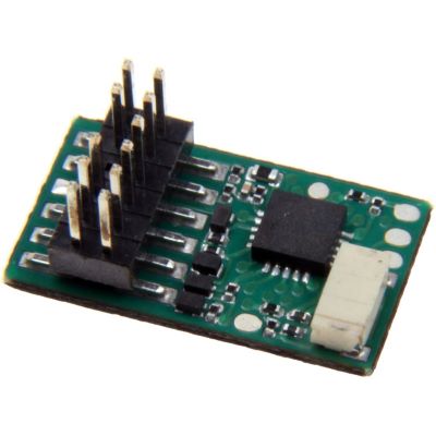
Suitable locomotive decoder for compatible TT vehicles.
View Product →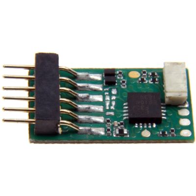
Digital auxiliary functions in suitable TT vehicles.
View Product →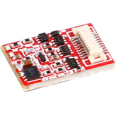
Compact function decoder for suitable coach circuit boards.
View Product →Decoders for common H0 interfaces, vehicle functions and higher current requirements.
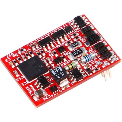
Multiprotocol decoder with modern motor control.
View Product →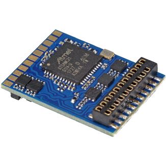
Motor control and numerous vehicle functions.
View Product →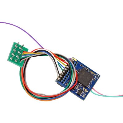
For driving trailers, lighting and models without a motor.
View Product →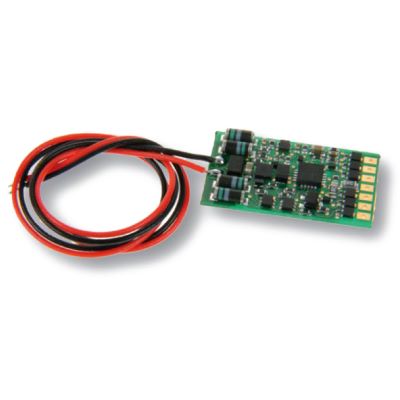
Switches, dims and flashes lighting functions.
View Product →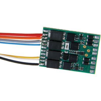
For vehicles with increased motor and function output requirements.
View Product →Powerful vehicle and layout modules for large motors, lighting, accessories and outdoor railways.
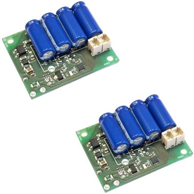
Digital lighting and auxiliary functions in large-scale vehicles.
View Product →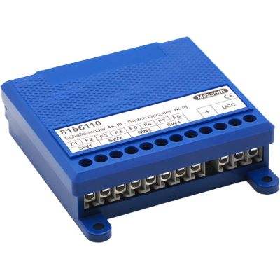
Four channels for turnouts, signals and lighting.
View Product →
Detects contacts for train reporting and automation.
View Product →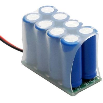
Bridges short interruptions in current collection in large-scale vehicles.
View Product →Stationary modules for turnouts, signals, occupancy detection, feedback and additional power districts.
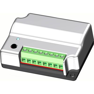
Controls turnouts, signals and suitable lighting.
View Product →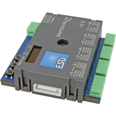
Configurable outputs and local OLED operation.
View Product →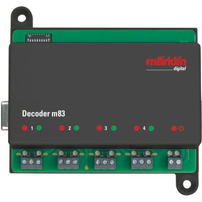
Controls up to four turnouts or other solenoid accessories.
View Product →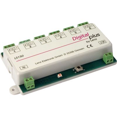
Controls turnouts, signals and other accessories.
View Product →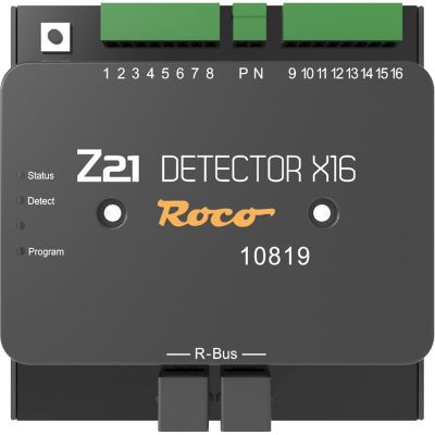
Detects multiple track sections and contacts.
View Product →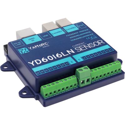
Sixteen current-sensing inputs for two-rail layouts.
View Product →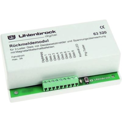
Monitors eight two-rail track sections.
View Product →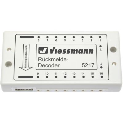
Feedback module for contacts and automated sequences.
View Product →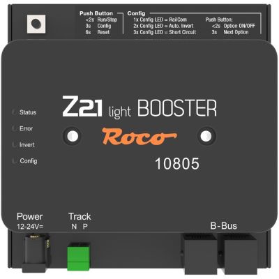
Additional power district with RailCom support.
View Product →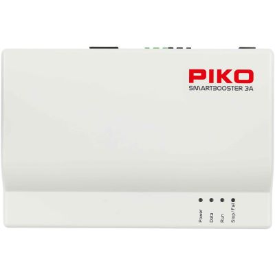
Expands a compatible SmartControl WLAN system.
View Product →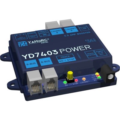
Galvanically isolated power expansion for digital layouts.
View Product →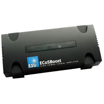
Powerful booster for the ESU system.
View Product →A digital command station, a suitable power supply and locomotives with compatible digital decoders are required. Accessory decoders and feedback can be added later.
This depends on the system and is not generally recommended. Fitting a locomotive decoder that is compatible with the command station is the safer solution.
A locomotive decoder has regulated motor control. A function decoder switches lighting or auxiliary functions but does not control a traction motor.
No. Twin-coil mechanisms, motor-driven mechanisms and servos require different output signals and switching times.
Feedback is important for staging yards, block operation, train tracking, automatic routes and computer control.
A booster is required when the command station does not provide enough power or the layout should be divided into several separate short-circuit districts.
No. A booster only increases the electrical power available for the digital signal.
No. LocoNet, XpressNet, s88N, R-Bus, CAN and ECoSlink use different protocols and electrical pin assignments.
DCC is a widely used digital protocol supported by many manufacturers. mfx is particularly closely associated with Märklin command stations and automatic locomotive registration.
RailCom allows compatible DCC decoders to return data through the track. Suitable detectors are required for location-specific identification.
No. Wi-Fi and LAN connect operating devices or computers to the command station. DCC, mfx or Motorola is then transmitted to the track.
An app can replace a handheld controller but not the digital command station and its track output. The command station, app and network must be compatible.
The overview separates vehicle decoders, layout modules, digital protocols, system buses and network connections according to their actual purpose.
Content status: 17 July 2026. Consult the current instructions, voltage specifications and compatibility information before installation and connection.
The main guide connects digital technology with gauges, layout planning, track, scenery, vehicles, repairs, maintenance and garden railways.