Test Before Closing
Complete all test runs before the tunnel and mountain shell are permanently closed.

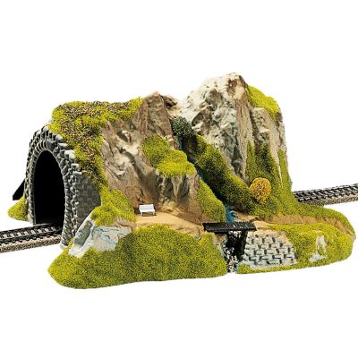
A convincing model railway tunnel begins with reliable track, sufficient clearance and safe maintenance access. Test long vehicles, curves and pantographs first. Then add the tunnel tube, inner walls, portal, removable mountain shell and realistic scenery.
Building a model railway tunnel begins with the track rather than the portal. The hidden route must safely accommodate every intended locomotive, long coach, multiple unit and, where applicable, raised pantograph. Only after this has been confirmed should the tunnel tube, inner walls, portal, mountain shell and vegetation be added.
A tunnel fulfils several functions. It allows trains to disappear into the landscape, separates different layout scenes and can visually calm a tightly curved route. At the same time, it creates an area that is difficult to inspect and must remain accessible for cleaning, repairs and the recovery of derailed vehicles.
A visible tunnel entrance consists of more than a portal front. Wing walls, a short section of tunnel lining, drainage, rock or an earth slope and a clean transition to the track bed create a convincing overall scene. A brightly lit layout room or uncovered wooden framework should not be visible behind the portal.
Complete all test runs before the tunnel and mountain shell are permanently closed.
Keep the wide vehicle body and the overhanging ends clear on every curved section.
Hidden track must remain reachable for cleaning, inspection and vehicle recovery.
Connect the portal visibly to wing walls, rock, soil and the lined tunnel interior.
A stable track support, reliable rail joints and sufficient power feeds form the technical foundation.
Vehicles, curved overhang, roof fittings and overhead-line equipment require free space along the complete route.
A tube, inner walls and a dark background prevent an open layout framework from being visible.
The opening, wing walls and masonry connections create the visible architectural entrance.
Mountain surfaces, rocks, soil, scree and vegetation connect the structure to the surrounding scenery.
The tunnel length, number of tracks, location of curves, railway era and landscape determine whether a single portal, a ready-made tunnel or a completely scratch-built tube is most suitable.
The portal forms the visible entrance. The mountain shell, interior lining and hidden route are built individually and can be adapted precisely to the track plan.
A compact solution for small layouts and dioramas. Internal dimensions, track position and maintenance access must be tested before permanent installation.
A corner tunnel conceals a curved route at the edge of a layout while using little space. Lateral clearance requires particular attention because of vehicle overhang.
A double-track portal requires the correct track centres. Two separate bores can be a convincing alternative for mountain routes and modern railway themes.
H0m, H0e, H0f, Nm and TTe represent smaller prototype profiles. The portal and interior must nevertheless provide sufficient curve clearance and maintenance access.
Smooth concrete surfaces, large cross-sections, safety walkways and modern overhead-line equipment suit main lines and high-speed routes of recent eras.
The portal opening alone does not prove that every train can pass safely. The decisive factor is the free space around the track, vehicle and pantograph throughout the complete tunnel route.
| Planning Area | What Must Be Checked? | Practical Test |
|---|---|---|
| Straight Track | Vehicle width, vehicle height, roof fittings and lateral access. | Move the largest intended vehicle slowly through a full-size portal template. |
| Track on a Curve | Overhang at the vehicle ends and inward movement at the vehicle centre. | Push and pull the longest bogie coach through the curve in both directions. |
| Narrow Gauge | Correct profile for H0m, H0e, Nm, TTe or another model gauge. | Select the narrow-gauge portal together with the dimensions of the intended vehicles. |
| Overhead Line | Contact-wire height, pantographs, supports and tunnel overhead-line construction. | Test with the pantograph fully raised or limited to its intended operating height. |
| Double-Track Route | Track centres, two long vehicles passing and the position of the side walls. | Position the two longest coaches simultaneously in the portal and curved section. |
| Portal Position | Curve radius, vehicle overhang and the visible tunnel interior. | Place the portal on straight track or a generous curve wherever possible. |
| Maintenance Space | Reach height, track cleaning, cable access and vehicle recovery. | Provide a removable mountain, rear opening or sufficiently large access hatch. |
The actual vehicle, selected radius, track system, portal opening and overhead-line equipment remain authoritative. A general clearance dimension cannot replace a practical test run.
The ends of a long coach can project beyond the outside of the track profile while the centre of the coach moves inward. Test the longest intended coach rather than only a short locomotive.
The construction and surface of the portal should suit the represented railway, era and region. A lined visible interior prevents the portal from looking like a flat scenic façade.
Natural-stone portals suit branch lines, mountain routes and older main lines. Joints, individual stains and an irregular transition into the mountain make the entrance more convincing.
Brick portals support industrial and urban themes. Concrete portals suit upgraded main lines, newly built tunnels and modern railway scenes.
Straight or curved inner walls line the area immediately behind the portal. A dark progression or gentle curve prevents a direct view into the open layout framework.
Walls visually retain the slope. Scree, a drainage channel, cable trough and a clean transition to the ballast make the tunnel entrance understandable.
Dark areas above the opening, moisture traces in the joints and restrained vegetation suggest use and exposure. A uniformly black surface usually looks artificial.
A fine separation line can be concealed behind rock, a wall, bush or terrain edge. Locating pins or magnets return the removable landscape section to the correct position.
The visible scale determines the size of the masonry and portal. The model track gauge additionally determines which vehicle profile must pass through the opening.
| Gauge | Typical Scale | Typical Model Track Gauge | Tunnel-Building Consideration |
|---|---|---|---|
| Z | 1:220 | 6.5 mm | Fine portals and small tunnel tubes still require an access opening that can be reached safely. |
| N and Nm | 1:160 | 9 mm or a narrower model gauge | Long vehicles create extensive landscape effects but require sufficient clearance on curves. |
| TT, TTm and TTe | 1:120 | 12 mm or a narrow-gauge variant | Select the portal explicitly for the intended TT or narrow-gauge profile. |
| H0 | 1:87 | 16.5 mm | A large selection of single- and double-track portals, interior walls and ready-made tunnels is available. |
| H0m, H0e and H0f | 1:87 | 12, 9 or 6.5 mm | The scenery remains H0-sized, while the narrower railway profile requires a suitably proportioned portal. |
| S, Sm and Se | 1:64 | 22.5 mm or a narrow-gauge variant | Portals and inner tubes are frequently constructed individually for the particular project. |
| 0, 0m and 0e | Usually approximately 1:45 | 32 mm or a narrow-gauge variant | Plan the large portal opening and wide maintenance access at an early stage. |
| 1, Im and Ie | 1:32 | 45 mm or a narrow-gauge variant | Tunnel shells are usually built in lightweight, stable and removable sections. |
| G, II and IIm | Prototype-dependent, frequently approximately 1:22.5 | Frequently 45 mm | Outdoor tunnels must be weather-resistant, drained and permanently accessible for inspection and cleaning. |
Track gauge, scale and clearance are separate considerations. Always test the selected portal with the actual vehicles intended for operation.
Portals, inner walls, ready-made tunnels, retaining walls and scenery materials from different manufacturers can be combined when the scale, opening and selected construction materials are compatible.



Filter the verified selection by gauge, manufacturer, number of tracks, application and product group. Every product card leads directly to the English version of the corresponding product page.

Natural-stone portal for a double-track H0 tunnel entrance.
View Product →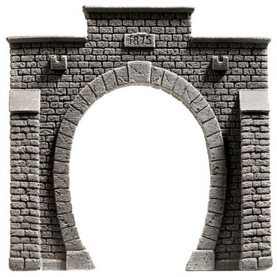
Classic single-track portal for an H0 main line or branch line.
View Product →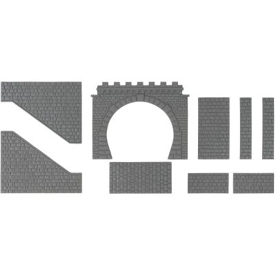
Portal kit for a broad H0 main-line tunnel opening.
View Product →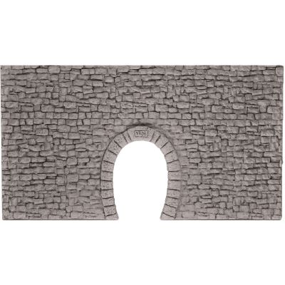
Rubble-stone portal for metre-gauge and narrower H0 railways.
View Product →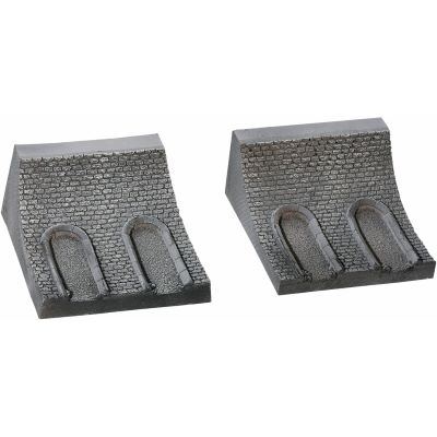
Lining for the visible interior section of a tunnel on a curve.
View Product →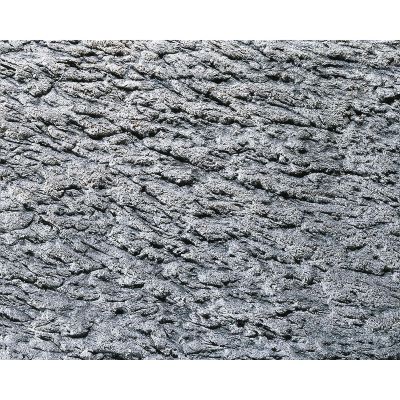
Formable rock texture for individual tunnel interior surfaces.
View Product →
Compact tunnel body for a straight single-track H0 route.
View Product →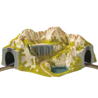
Ready-made landscape form for concealing an H0 corner curve.
View Product →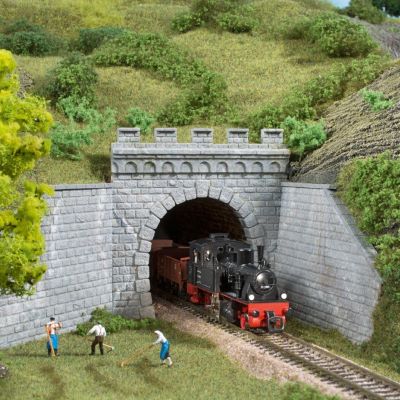
Two portals for TT routes with steam or electric operation.
View Product →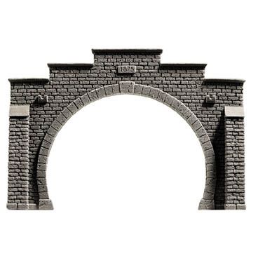
Compact stone portal for a double-track N-gauge route.
View Product →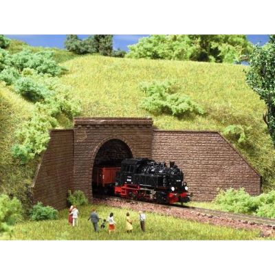
Portals for straight or curved single-track N-gauge entrances.
View Product →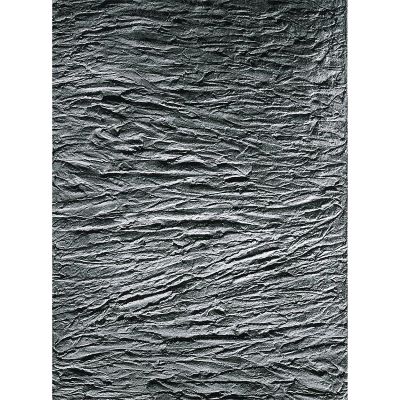
Structured interior lining for compact Z-gauge tunnels.
View Product →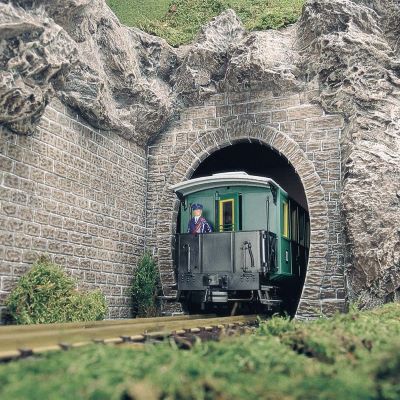
Large-format portals for garden railways and large-scale scenery.
View Product →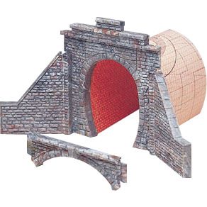
Large portal opening for different types of H0 railway operation.
View Product →Check the gauge, number of tracks, curve radius, longest vehicle and overhead-line requirements before permanently installing the portal, tunnel tube and mountain.
Tunnel portals, ready-made tunnels, inner walls and tunnel tubes.
Wing walls, structural sheets, hard foam and surface materials.
Materials for mountain transitions, rocks and portal edges.
Railway structures for valleys, underpasses and mountain routes.
The technical foundation of the visible and hidden railway route.
Contact wire, masts and components for electric train operation.
Adhesives for hard foam, plastic, wood and landscape materials.
Colour joints, soot, moisture traces, masonry and surrounding rock.
This construction sequence keeps the hidden route open for as long as possible and separates technical testing, interior construction and landscape design.
Determine the tunnel entrance, hidden route, possible access openings and transition into the surrounding landscape.
Test both directions, pushed trains, passing vehicles and, where applicable, the intended pantograph position.
The track, rail joiners and wiring must operate reliably before any permanent landscape construction begins.
The opening must permit track cleaning, repairs and the safe removal of the longest intended vehicle.
Before applying adhesive, check the vehicle clearance, wing walls and transition between the portal and mountain.
Give the area visible through the portal a dark, structured surface that matches the selected portal.
Rigid foam, mesh or a lightweight framework forms the mountain shell without blocking the maintenance route.
After a final test run, add joint colour, operational staining, soil, rock fragments and suitable plants.
Dust, abrasion and small remains of scenery material also collect on hidden track. The tunnel therefore requires an unobstructed cleaning route. Loose plaster fragments, scatter material and cables must not hang above the track.
Turnouts and complicated track connections should preferably not be positioned beneath a fixed mountain. When this cannot be avoided, the complete area must remain accessible from above, below or behind.
A simple service light or camera can make inspection easier but cannot replace a physical access opening. Garden-railway tunnels additionally require drainage, frost-resistant construction and protection against leaves and other outdoor debris.
The longest coach determines the lateral space required on a curved route.
Every hidden location must remain safely reachable by hand.
Contact wire, pantographs and tunnel supports require additional height and maintenance access.
An inner wall, dark screen or curved route creates convincing visual depth.
The portal, inner walls, overhead-line equipment and removable mountain can alter previously available space. Test the complete train formation again after every significant construction step.
These answers cover portal dimensions, track position, overhead lines, narrow-gauge tunnels, maintenance access and realistic landscape design.
This depends on the scale, vehicle profile, curve radius, track centres and overhead-line equipment. Test the portal and tunnel tube with the largest vehicles that will actually be used.
Yes, provided additional lateral clearance is available. Straight track or a generous curve is generally safer and often more prototypical.
Push and pull the longest coach slowly through the curve. Neither its ends nor its centre may touch the portal or inner walls.
Contact-wire height, pantographs and supports require additional space. Test the pantograph in the intended operating position before closing the tunnel.
At least the area visible from the normal viewing position should be lined. A dark progression prevents the open framework and cables from being visible.
It must permit the longest vehicle to be gripped and removed safely while also providing access to the track, cables and any turnouts.
Only when it remains completely accessible. A position outside the fixed mountain shell or beneath a clearly removable section is preferable.
Ready-made tunnels can be installed quickly. A scratch-built tunnel can be adapted more precisely to the track plan, radius, landscape and maintenance access.
Not necessarily. The visible area should nevertheless be lined and the background made sufficiently dark that no open framework remains visible.
Both use the 1:87 scenery scale but represent narrow-gauge profiles. Dedicated narrower portals and matching interior components are available.
Yes. The curve must still provide reliable running, adequate lateral clearance and full internal access for maintenance.
An accessible opening, low-dust scenery work and regular track cleaning are more important than a completely sealed tunnel tube.
Check the track, clearance, overhead line and maintenance access. Then complete the entrance with a suitable portal, inner walls, removable mountain shell and realistic vegetation.
Content reviewed and updated on 16 August 2026. Product dimensions, vehicle data, track geometry and each manufacturer’s processing instructions remain authoritative.