Identify the Decoder
Determine the manufacturer, type, supported protocols and exact decoder designation whenever possible. Compare the vehicle instructions with the decoder manual.

Change the locomotive address, improve starting behaviour, adjust braking distances, limit maximum speed, assign lighting functions or configure a sound decoder: with the right sequence, complicated CV numbers become a logical locomotive setup.
This programming workshop takes you from a safe programming track through CV1 and CV29 to function mapping, sound projects, manufacturer-specific programmers and systematic troubleshooting.
Programming a vehicle decoder means changing settings stored inside the decoder. In the DCC system, these memory locations are called Configuration Variables, or CVs. Some basic CVs are standardised, while many advanced settings are defined by the decoder manufacturer.
You should therefore never transfer an arbitrary CV list from the internet to every decoder. CV1 is normally used for the short primary address of a DCC multifunction decoder, CV17 and CV18 store a long address and CV29 combines several important operating options. Motor parameters, light dimming, function mapping and sound settings can vary significantly between ESU, ZIMO, PIKO, Märklin, Uhlenbrock, Lenz and other manufacturers.
The safest procedure therefore consists of three parts: identify the decoder, save the original settings and change only one value at a time. If five CVs are changed simultaneously and the locomotive then runs worse, it becomes difficult to identify which change caused the problem.
A dedicated programming device is not required for every locomotive. A suitable digital command station can read and write many basic CVs. Manufacturer-specific programmers become particularly useful for extensive function mapping, sound projects, firmware updates and frequently repeated configurations.
Begin with identification and addressing. Driving behaviour, functions and sound come afterwards. This keeps every change traceable.
Determine the manufacturer, type, supported protocols and exact decoder designation whenever possible. Compare the vehicle instructions with the decoder manual.
Use a short, clean track that is electrically isolated from the rest of the layout. Place only the vehicle being programmed on the track.
Read the address, CV29 and important driving parameters. When using programmer software, save the complete project whenever possible.
Use CV1 for a short DCC address. For long addresses, preferably let the command station calculate and write CV17, CV18 and the corresponding CV29 setting.
Adjust starting voltage, acceleration, braking delay and maximum speed gradually and test after every change.
Assign function buttons, AUX outputs, shunting mode, cab lighting and other functions systematically.
Check the sound project, loudspeaker and decoder family. Transferring new sound files usually requires a compatible manufacturer-specific programmer.
Test both directions, low-speed running, braking, lighting and all functions. Save or record the final configuration.
Modern command stations normally perform these calculations automatically. The workbench still shows what happens inside the decoder and can help with troubleshooting. It applies to suitable DCC multifunction decoders; the instructions for the particular decoder remain authoritative.
Extended DCC addresses from 128 to 10239 are stored in CV17 and CV18. Long-address mode must additionally be activated using bit 5 of CV29.
CV17 = 192 · CV18 = 218 · activate bit 5 in CV29.
Using the dedicated address function on your command station is normally more convenient and safer because it can configure CV17, CV18 and CV29 together.
CV29 is not a single switch. It combines several bits. This calculator covers the common DCC multifunction-decoder options represented by bits 0 to 5.
Normal direction · 28/128 speed-step mode · short address.
Manufacturers may impose additional dependencies or limitations. Always read the existing CV29 value and consult the decoder manual before writing a new value.
The following CVs provide a useful orientation. Not every decoder implements every optional CV in exactly the same way. Manufacturer documentation is particularly important beyond the core DCC variables.
Stores the short primary address of a DCC multifunction decoder. Long addresses are not written as one large value into CV1.
On decoders that support it, use the lowest value that allows the locomotive to start reliably and smoothly.
On conventional DCC decoders, this controls the acceleration delay. Manufacturers may scale values differently.
Higher delay values can create smoother braking but require more anticipation during operation.
An optional DCC CV used for maximum speed on compatible decoders. Not every decoder implements it identically.
On compatible decoders, CV2, CV6 and CV5 can form a simple three-point speed curve.
These values can help identify the decoder. Factory-reset procedures involving CV8 are manufacturer-specific; never assume one universal reset value.
Together they store the extended DCC address. Long-address mode must additionally be activated in CV29.
On compatible DCC decoders, CV19 can be used for Advanced Consisting or multiple-unit operation.
On compatible decoders, this CV is used to configure aspects of bidirectional DCC communication.
Combines settings including direction, speed-step mode, alternative power sources, bidirectional communication, speed tables and address type.
Various modern decoders use these CVs to access extended CV areas. Their application is manufacturer-specific.
An electrically isolated programming track is the preferred environment for identification, reading and basic changes. It helps prevent other vehicles from accidentally receiving the same programming command.
Programming on Main addresses a specific decoder on the main track. This allows driving parameters to be adjusted during testing. Whether values can also be read depends on the decoder, command station and available feedback technology.
Graphical programming tools replace many individual CV entries with menus. Depending on the system, they can also save projects, update firmware, transfer sounds and configure complex function assignments.
DCC provides a shared technical basis, but manufacturers use their own mapping logic, sound formats, firmware functions and programming tools. Manufacturer-specific documentation is therefore particularly valuable for advanced configuration.
A programmer is particularly useful when vehicles are digitised regularly, function assignments are changed, sound projects are transferred or decoders are tested outside the locomotive. The decisive factor is which decoder families the particular device actually supports.
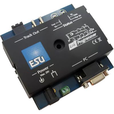
Graphical configuration, function mapping and sound projects for compatible ESU LokPilot and LokSound decoders.
View Product →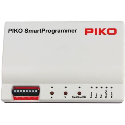
Conveniently configure compatible SmartDecoders, transfer suitable sound projects and test vehicle functions.
View Product →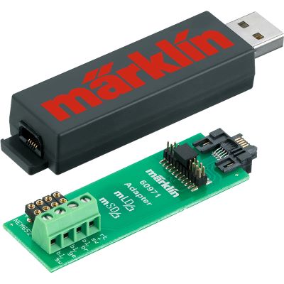
PC programming device for compatible Märklin retrofit decoders, including configuration and sound-project editing.
View Product →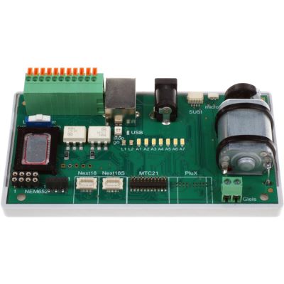
Read, program and test decoders outside the locomotive using several common decoder interfaces.
View Product →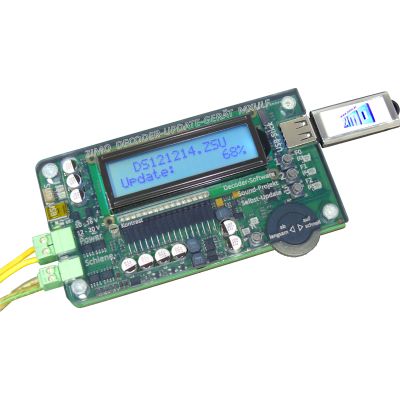
CV programming, firmware maintenance and sound-project transfer for compatible ZIMO decoder families.
View Product →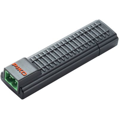
Compact USB programming interface for compatible PIKO SmartDecoder XP projects and settings.
View Product →Standardised DCC CVs can often be read and written using many digital command stations. Sound files, firmware updates and graphical project files are usually tied to specific manufacturers and decoder families. Always check the current compatibility list of the programming device before purchase.
Basic DCC programming logic does not depend on model scale. The differences arise from installation space, motor current, output requirements, heat generation and the interfaces used.
| Gauge World | Typical Decoders | Particularly Important When Programming |
|---|---|---|
| Z Gauge | subminiature and direct-wired decoders | component size, heat generation and suitable track voltage |
| N Gauge | Next18, NEM 651 and micro decoders | compact dimensions and limited thermal reserves |
| TT / TTe | Next18, PluX12 and NEM 651 | motor control and available function outputs |
| H0 / H0e / H0m / H0f | NEM 652, 21MTC, PluX, Next18 and wired decoders | protocol, interface and actual vehicle current |
| Gauge 0 | high-output locomotive and sound decoders | motor current, loudspeaker and additional electrical consumers |
| Gauge 1 / G | large-scale and XL decoders | programming current, multiple motors, smoke generators and high loads |
Check the programming track, wheel contacts and electrical pickup. Not every decoder or protocol supports every reading method.
Test the old and new addresses. With a long DCC address, also check whether extended addressing has been activated in CV29.
Check the wiring and installation first, then inspect CV29 or the decoder's direction setting. Do not change two possible causes at the same time.
Reduce excessive changes to starting voltage or motor control and inspect the mechanism and current pickup.
Compare the mapping with the actual AUX outputs. Do not confuse logic-level outputs with amplified function outputs.
Check the programmer, software version, decoder family and project file. Do not interrupt the power or USB connection while writing.
The product search reads current English product categories and manufacturer pages from Modellbahnshop. Discovered product pages are checked before display. Archived products are excluded, small preview images are normalised to the 400-pixel shop version and delivery information is deliberately not copied to the product cards.
Live checking will begin when you approach this section.
A good locomotive configuration is created step by step. After the address and basic driving behaviour come motor tuning, lighting, function mapping, sound and, where applicable, buffer storage. Detailed guides are available for each stage.
In the DCC system, CV stands for Configuration Variable. A CV stores a decoder parameter such as an address, acceleration value or another configuration setting.
The short DCC address is normally managed through CV1. Long DCC addresses use CV17 and CV18 and require the corresponding long-address setting in CV29.
On suitable DCC multifunction decoders, CV29 combines several core settings including direction, speed-step mode, alternative power-source conversion, bidirectional communication, speed-table selection and short or long addressing.
Normally not. Modern digital command stations can enter a long address conveniently and configure CV17, CV18 and the address option in CV29 together.
Programming on Main, or PoM, allows selected decoder values to be changed on the main track by addressing a particular locomotive. It is especially useful for test runs and fine-tuning.
In Service Mode, an electrically isolated programming track helps prevent other vehicles from accidentally receiving the same programming commands. It is also useful for diagnosis and CV reading.
No. Basic DCC CVs can often be adjusted with different command stations. Sound projects, firmware updates and graphical project functions are usually manufacturer-specific.
There is no safe universal reset value for every decoder. Use only the reset value specified in the instructions for the exact decoder model and manufacturer.
Common causes include poor current pickup, dirty wheels, an unsuitable programming method or a decoder or protocol that does not support the selected reading method.
With suitable DCC decoders and command stations, many values can be written using PoM during operation. Which CVs can be changed meaningfully depends on the decoder.
CV2, CV3 and CV4, and on compatible decoders CV5 and CV6, are traditional starting points. Modern motor-control systems also use manufacturer-specific parameters that should only be changed according to the decoder instructions.
Record at least the decoder manufacturer, decoder type, address, CV29 and important changed values. When using a manufacturer-specific programmer, also save the complete project file.
The comprehensive Model Railway Guide connects decoders, digital command stations, interfaces, electrical systems, track, vehicles, maintenance and layout planning into one complete knowledge base.