Our cookies offer you a fast, relaxed and full-featured shopping experience. Some are necessary to operate the website and its functions. Others help us to improve our services. If you agree to this, simply consent to the use of cookies for preferences, statistics and marketing by clicking on "OK". Alternatively, you can deactivate individual cookies under "Customise cookies" or all cookies, except those required for the function of our website, under "Reject all".
Layout Planning · Room for Every Train
Planning Track Spacing and Clearance Profiles Correctly
Unobstructed running starts beside the track. Plan passing movements, platforms and clearances before ballast, tunnel portals and overhead lines are fixed in place.
Planning track spacing and clearance profiles correctly means first positioning the track centrelines, then checking the space needed by vehicles and structures. On straight track, the guidance in MOROP recommendation NEM 112 is useful. Curves introduce vehicle overhang. Platforms, tunnels and overhead lines each need their own clearance checks. The vehicles, radii and track systems you actually use are decisive.
Track-centre spacing
This is the distance from the centre of one track to the centre of the adjacent track. It is neither the distance between the two rails of a track nor the clear gap between vehicle bodies. On parallel tracks of the same gauge, it can also be measured between corresponding rails.
Clearance profile
The clearance profile, or structure gauge, defines the cross-section that must be kept clear along the route. Buildings, railings and rocks must not intrude into the required passage. The reference lines are the track centreline and railhead level, not the baseboard. The vehicle envelope, by contrast, describes the space occupied by the vehicle.
Show these two dimensions separately on your track plan. Generous spacing between parallel tracks will not solve a problem with a tunnel that is too low. Equally, a wide tunnel opening does not guarantee that two long passenger coaches can pass each other safely.
Look It Up Rather Than Guess
Track spacing on straight standard-gauge lines
The following values come from MOROP NEM 112, 2024 edition. They are recommended track-centre spacings in millimetres and should not be reduced if possible. The station values do not include a general allowance for an island platform.
Straight standard-gauge track: track-centre spacings according to MOROP NEM 112 (2024), all dimensions in mm
Nominal size
Open line
Station
Z
19 mm
21 mm
N
25 mm
28 mm
TT
34 mm
38 mm
H0
46 mm
52 mm
S
63 mm
71 mm
0
89 mm
103 mm
I
125 mm
141 mm
II
178 mm
200 mm
This table applies to straight standard-gauge track. Narrow-gauge systems such as H0e, H0m and TTm, as well as garden railways, require separate classification: G scale on 45 mm track is not automatically nominal size II with 64 mm standard-gauge track. NEM 104 forms part of narrow-gauge railway planning. Special loads and unusual vehicle envelopes also need separate checks.
Distinguish track-system geometry from standard recommendations
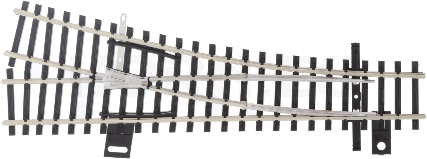
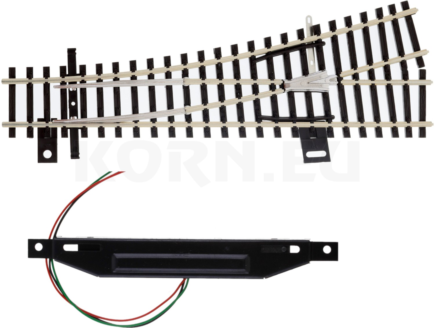
Ready-made turnouts and curves produce the track geometry specified by the manufacturer. In the C Track system, for example, you will encounter 77.5 mm spacing and 64.3 mm with the slim geometry. These are system dimensions, not universal minimum spacings for H0. Check the particular combination against the track plan. Flexible track allows you to choose the spacing, but requires careful alignment and fixing.
The body of a long coach forms a straight connection between its bogies on curved track. Its centre moves towards the inside of the curve, while its ends can swing outwards. You therefore need to consider both vehicles as they pass. On a tight double-track curve, a successful test with a single vehicle on just one track is not enough.
MOROP NEM 103, 2024 edition covers the widening of the clearance profile on curves. The radius and vehicles determine the requirement. For the distance between adjacent tracks, use NEM 112. Do not simply add its values to the widening dimensions in NEM 103 without checking: the two tables address different questions.
Example: long H0 coaches
For an inner track curve radius of 500 mm, NEM 112 gives a track-centre spacing of 59 mm for vehicle group C. Classification in group C follows NEM 301. This table entry does not establish suitability for every H0 vehicle or for other radii; special models and manufacturers' specifications must also be checked.
Choose the correct vehicle group
Groups A, B and C in MOROP NEM 301, 2024 edition differ in effective bogie pivot spacing and vehicle width, among other characteristics. Select the group using vehicle dimensions, rather than the label “passenger coach” or “freight wagon”. Shortened models may belong to a different group from full-length scale models of the same prototype.
Also check the transition from straight to curved track. The required track spacing must already be fully present at the start of the curve; fixed objects also need the specified transition clearance. Trial assembly is particularly useful for reverse curves, superelevation or a simultaneous change of gradient. The page Minimum Curve Radii for H0, TT, N and Other Gauges helps you choose suitable radii.
Platform · Portal · Contact Wire
Mark clearance restrictions deliberately on the plan
Platforms and loading ramps
For an island platform, track-centre spacing consists of three dimensions: the distance from the first track centreline to the platform edge, the platform width, and the distance from the second edge to the second track centreline. The two lateral offsets depend on height, vehicles and track alignment. A platform kit therefore cannot be chosen solely by its stated gauge.
On curves, the gap between the vehicle and platform edge changes along the coach. Check the centre of the body, doors, steps and vehicle ends. Start with a cardboard surface at the planned height. Only finalise the edge, canopy and accessories once all critical vehicles pass without contact. Find suitable ideas under Platforms.
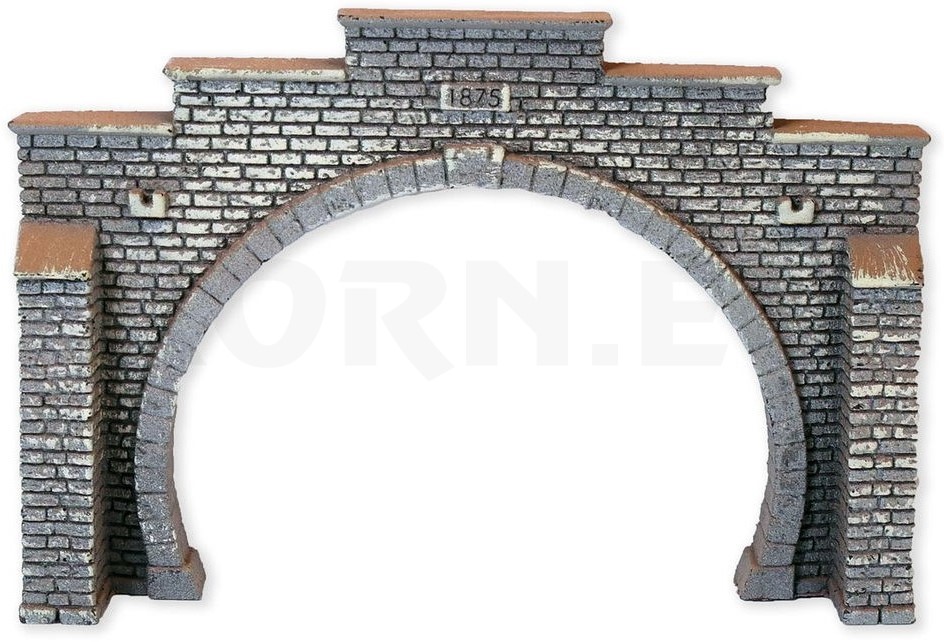
Measure the usable opening above the finished railhead level. The track base, insulation, roadbed and rail profile all affect the height. For portals on curves, the front edge is not the only concern: a thick portal wall or a narrow tunnel entrance can contact the vehicle body further inside. Plan removable sections and access to hidden track.
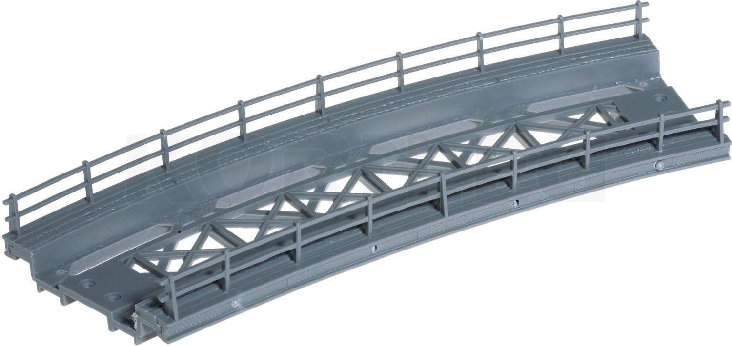
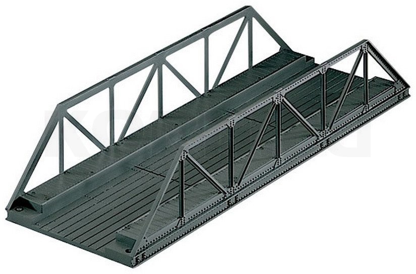
On bridges, pay particular attention to internal girders, railings, deck structures and cross-bracing. A nominally double-track bridge must suit your actual track spacing. Check clearance before gluing, then repeat the test after fitting the final details. Use the guides Building Tunnels and Choosing Tunnel Portals to help with your selection.
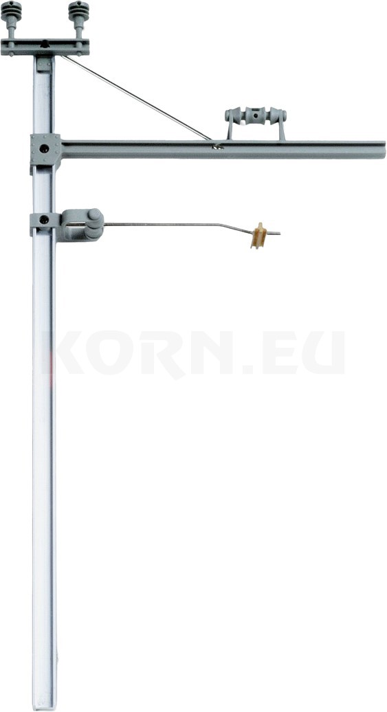
Raised pantographs need their own working space above the vehicle roof. Contact wire, fittings and support structures must all be included in the cross-section. NEM 102 refers to NEM 201 and 202 for this purpose; beneath bridges and in tunnels, the construction height of the overhead system must be added to the relevant vertical clearance. A measurement taken from the baseboard would be unsuitable.
Before construction, decide whether pantographs will run in contact with the wire, raised to a limited height or lowered. A portal that works with lowered pantographs may become too tight after a later conversion. Slowly test entrances, wire transitions and height changes with the locomotives intended for the route.
Transfer heights from a strip resting on the rails or from a suitable measuring aid. This keeps the measurement clear even when tracks with different roadbeds are used.
Record measuring points
Note the track, radius, spacing, clear height and critical vehicle. Photos with a measuring scale in place help when making later changes.
Check again after changes
Even additional lamps, signs or a change in track position can reduce previously adequate clearance.
From Screen to Track Base
Track-centre template and platform calculator
Choose a nominal size and download an SVG drawing of two straight track centrelines. The two axes are set at the selected spacing. Open the file and print it at 100% or actual size. Then measure the 50 mm check line. Automatic page scaling would alter the dimensions.
H0: 46 mm track-centre spacing on a straight open line.
The template marks track centrelines; it is not a clearance gauge and does not confirm suitability for curves. For the complete clear cross-section, use the drawing and dimension table in MOROP NEM 102, 2019 edition, together with the standards relevant to your situation.
Island platform: add the space requirements
30 + 80 + 30 = 140 mm track-centre spacing.
The preset numbers are an illustrative example only. Replace them with the dimensions established for your project. The calculation adds the space requirements; it determines neither permissible platform-edge offsets nor a platform height that complies with the standards. Stairs, supports and a canopy must also fit independently.
Check First, Add Scenery Later
Six steps to adequate clearance
Define your rolling stock. Consider the longest coaches, wide locomotives, projecting parts, couplings and special loads. Deliberately allow for planned additions to your fleet.
Lay the track temporarily. Build straight sections, the tightest curve and transitions using the final roadbed. Mark the track centrelines at several points.
Mock up structures in cardboard. Represent platform edges, portal thickness and bridge girders in their planned positions. Secure the cardboard against accidental movement.
Test passing movements. Slowly move critical vehicles past each other on both tracks at the same time. Include both directions of travel, both vehicle orientations and propelled trains.
Adjust restricted areas. Change the track spacing, radius or position of structures. Do not test only the vehicle that happens to be on the layout at the time.
Check the finished arrangement. Test again after ballasting, fixing, lighting and detailing. Keep hidden areas accessible for later cleaning and recovery of derailed vehicles.
Trial assembly is particularly useful when planning a helix or a hidden staging yard. These combine tight curves, multiple levels and difficult access. Vehicle clearance and room for your hand are separate requirements: a locomotive may fit through even though a derailed coach is almost impossible to reach.
Spot common planning mistakes early
Avoid measuring from sleeper edge to sleeper edge, applying an H0 value to narrow gauge without checking, or treating a catalogue's external dimensions as the clear portal opening. Raising the track later beneath an already installed bridge is another potential problem. Marked reference points and a short test section reveal these issues before the scenery is finished.
From Plan to Component
Find track and suitable accessories
Filter the selection by category and gauge. The text search checks loaded product names and MBS item numbers. More results can be loaded from the shop categories. Before choosing an item, compare the installation dimensions on its product page.
Manufacturers of track, portals and overhead lines
Compare track geometry and installation dimensions within your chosen system. For structures, the actual clear opening matters; for overhead lines, consider the complete assembly. The manufacturer pages lead to product ranges and specifications in the Modellbahnshop.
Layout Planning Questions
What else matters before final installation?
Is 46 mm always sufficient in H0?
No. This value applies to a straight open line according to NEM 112. Curves, platforms, special vehicles and the geometry of your track system may require greater spacing. Check the actual installation.
Can I measure the gap between two coaches?
This is a useful practical test, but it does not replace the track-centre measurement. Vehicle width, overhang and lateral play affect the visible gap. Record the track positions and the vehicles used together.
Is the longest passenger coach enough as a test vehicle?
It is important, but is not always the only deciding factor. A wide locomotive, steps that swing out, a rail crane or a special load may be more critical elsewhere. Assemble a small selection of your most demanding vehicles.
How much extra clearance should I allow?
There is no universal allowance that covers every project. Consider construction accuracy, lateral vehicle play, planned details and future access. The allowance should be justified for your layout, rather than described as a general standard value.
Can a home-printed clearance gauge help?
Yes, provided the drawing, scale, print dimensions and intended application are correct. Check a paper printout or 3D print with a measuring tool. A gauge for straight track must not be used unchanged to confirm clearance on tight curves. The track-centre template on this page serves a different purpose.
Standards and technical background
The NEM information refers to MOROP. Special vehicles and non-standard systems require supplementary manufacturer documentation. Sources and link destinations were checked on 4 November 2026.
Cookies are small piece of data sent from a website and stored on the user's computer by the user's web browser while the user is browsing. Your browser stores each message in a small file, called cookie. When you request another page from the server, your browser sends the cookie back to the server. Cookies were designed to be a reliable mechanism for websites to remember information or to record the user's browsing activity.
Necessary
More information
Technically required cookies ensure that you can view our website and navigate in our offers. Basic functions such as filling the shopping cart, login or the display and selection of products on our websites are not possible without them.
Preferences
More information
Cookies are used here to make your visit to our website as convenient as possible. Already confirmed information or personal settings will be saved during your next visit. Cookies also enable functions such as the display of recommendations or the creation and administration of wish lists. This applies to both registered users and guests without an account.
Marketing
More information
We store information about your user behavior on our website and use this data for individual offers and campaigns in the context of direct marketing and for more comfort when using our website. These cookies are used, for example, to present you with special offers on the website itself or in mailings. Furthermore, we want to make surfing on our website as attractive as possible for you. The responsibility and control for data processing lies with us.
Statistics
More information
We use cookies for statistical purposes in order to better understand your user behavior and to support you in your navigation on our offer pages. This also enables us to record your navigation on our offer pages and to use this information for the design of our services to meet your needs.